No Copy


No Right Click

Selamat Datang di Situs Belajar PLC dan SCADA

Blog gratis yang menyajikan berita seputar PLC dan SCADA.

Microsoft Windows 10

Berita seputar Microsoft Windows 10. Membahas berbagai informasi mengenai Microsoft windows terbaru.

Apple OSX

Artikel yang membahas tentang OSX terbaru dari Apple tentu sangat menarik untuk dibaca. Tak kalah serunya jika kita paham mengenai tips dan trik yang ada didalamnya.

Photography

Photography asik dan menarik jika kita mengetahuinya lebih dalam. Disini kita bisa melihat berbagai hal dari sudut pandang photo. Menarik untuk dipahami.

Showing posts with label plc. Show all posts

Saturday, April 18, 2020

Links Of PLC

This is the links address for PLC Maker.
Please click below, which brand of PLC or Control System Integrator you prepare..!

ABB/Elsag Bailey/Alfa Laval
Alfa Laval/ABB/Elsag Bailey
Allen-Bradley
ALSTOM/Cegelec
Aromat/Matsushita
Array Electronics
AutomationDirect/PLC Direct/Koyo/
B&R Industrial Automation
Bachmann
Beck Electronic/Festo
Beckhoff
Berthel gmbh
Bosch
Bristol Babcock
Cegelec/ALSTOM
CNI
Control Microsystems
Crouzet Automatismes
Control Technology Corporation
Cutler Hammer/IDT
Delta
Divelbiss
Eberle/GE-Fanuc (Europe)
Elsag Bailey/ABB/Alfa Laval
Elsist
Entertron
Fatek Automation
Festo/Beck Electronic
FF Automation
Fisher & Paykel
Fuji Electric
GE-Fanuc
GE-Fanuc/Eberle (Europe)
Gefran/SIEI
Giddings & Lewis
Gould/Modicon
Groupe Schneider
Hima
Hitachi
Honeywell
Horner Electric
Ibercomp
Idec
IDT/Cutler Hammer
Industrial Control Links
International Parallel Machines
Jetter gmbh
Keyence Corporation
Kirchner Soft
Klockner-Moeller
Koyo/AutomationDirect/PLC Direct
LG Industrial Systems
Liyan Electric
Matsushita (Europe)/Aromat
Messung
Microconsultants/SPLat
Mitsubishi
Modicon/Gould
Moore Products/Siemens
Nyquist/P8
Omron
Opto22
P8/Nyquist
Pilz
Pixsys
PLC Direct/Koyo/AutomationDirect
Poscon
Reliance
Rockwell Automation
Rockwell Software
RTP Corporation
SAIA-Burgess
Schleicher
Schneider Electric
Selectron
Sharp
Shihlin
SIEI/Gefran
Siemens/Moore Products
Sigmatek
Sixnet
SMAR
SoftPLC/Tele-Denken
SPLat/Microconsultants
Square D
Teco a. s.
Tele-Denken/SoftPLC
Telemecanique
Toshiba
Toyoda/Toyopuc
Triangle Research
Triconex
Unitronics
Yokogawa
The PLCopen(IEC 61131-3)

Friday, November 13, 2015

Simatic ET 200SP CPU / ET 200SP Open Controller

Compact controllers for distributed applications

The new Simatic ET 200SP CPU Distributed Controller is a modular distributed controller that is compact and flexible. Thanks to its compact design, it requires little space in the control cabinet. Because it has the same storage systems, volumes, and features as the Simatic S7-1511 and S7-1513 CPUs, customer programs with varying design types can be used. Three Industrial Ethernet ports with variable bus adapters (RJ45, FC, SCRJ) have been integrated for flexible bus connection. Option handling in the central configuration also makes it possible to flexibly retrofit options without engineering effort. 

Source from: siemens.com

The distributed controller series is rounded off with the first 1510SP F CPU and 1512SP F CPU for modular and failsafe automation. This makes it possible to implement standard and failsafe applications using one controller in the ET 200SP. Another benefit is its high investment protection, because once a user program has been developed, TIA Portal makes it possible to easily port the program to both Simatic S7-1200 and Simatic S7-1500 controllers. The compact Simatic ET 200SP Open Controller is another addition to the modular distributed controller series and is particularly suited for series machine manufacturing. It is the first controller of this type to combine the functions of a PC-based Software Controller with visualization, Windows applications, and centralized I/Os in a single compact device. 

This means that users need to stock fewer spare parts, and evaluation and maintenance efforts are also significantly reduced. The Open Controller can be flexibly expanded with standard ET 200SP modules and can be optimized for series machines and machines with a distributed structure. Because it has a compact design, it requires little space in the control cabinet. It is also fully compatible with ET 200SP CPU projects, so various performance requirements can be met without additional effort. siemens.com/distributed-controller siemens.com/open-controller.

New Feature

• ET 200SP Open Controller: powerful all-in-one device with small footprint on the DIN rail 
• Very compact system with minimum space requirements in the control cabinet
• Modular expansion of functions with all ET 200SP modules 
• Complete engineering in TIA Portal for increased productivity with reduced engineering effort
• Failsafe CPUs 1510SP F and 1512SP F

Saturday, August 29, 2015

What can a PLC do? Why do we use them?

The meaning of PLC…

“PLC” means “Programmable Logic Controller”, that’s clear. The word “Programmable” differentiates it from the conventional hard-wired relay logic. It can be easily programmed or changed as per the application’s requirement. The PLC also surpassed the hazard of changing the wiring.
The PLC as a unit consists of a processor to execute the control action on the field data provided by input and output modules. In a programming device, the PLC control logic is first developed and then transferred to the PLC.
So, what can a PLC actually do?
  1. It can perform relay-switching tasks.
  2. It can conduct counting, calculation and comparison of analog process values.
  3. It offers flexibility to modify the control logic, whenever required, in the shortest time.
  4. It responds to the changes in process parameters within fractions of seconds.
  5. It improves the overall control system reliability.
  6. It is cost effective for controlling complex systems.
  7. It trouble-shoots more simply and more quickly
  8. It can be worked with the help of the HMI (Human-Machine Interface) computer
There are many other things this little ‘mean’ thing can do, but one thing I’m sure – that PLCs are irreplaceable in many industry applications and control projects.
Here is an example of wired ABB’s AC500 programmable logic controllers.
Wired ABB's PLCs
Figure 1 – Wired ABB’s PLCs (photo credit: us.profinet.com)

Basic block diagram

Figure 1 shows the basic block diagram of a common PLC system.
Block diagram of a PLC
Figure 2 – Block diagram of a PLC

As shown in the above figure, the heart of the “PLC” in the center, i.e., the Processor or CPU (Central Processing Unit).
  • The CPU regulates the PLC program, data storage, and data exchange with I//O modules.
  • Input and output modules are the media for data exchange between field devices and CPU. It tells CPU the exact status of field devices and also acts as a tool to control them.
  • A programming device is a computer loaded with programming software, which allows a user to create, transfer and make changes in the PLC software.
  • Memory provides the storage media for the PLC program as well as for different data.

Size of the PLC system

Usually they are classified on the basis of their size:
  • A small system is one with less than 500 analog and digital I/Os.
  • A medium system has I/Os ranging from 500 to 5,000.
  • A system with over 5,000 I/Os are considered large.

Components of the PLC system

CPU or processor: The main processor (Central Processing Unit or CPU) is a microprocessor-based system that executes the control program after reading the status of field inputs and then sends commands to field outputs.
I/O section: I/O modules act as “Real Data Interface” between field and CPU. The PLC knows the real status of field devices, and controls the field devices by means of the relevant I/O cards.
Programming device: A CPU card can be connected with a programming device through a communication link via a programming port on the CPU.
Operating station: An operating station is commonly used to provide an “Operating Window” to the process. It is usually a separate device (generally a PC), loaded with HMI (Human Machine Software).

PLC Configurations

There are two basic configurations that commercial manufacturers offer:
1. Fixed Configuration
Fixed PLC configuration

2. Modular Configuration
Modular type PLC 'SLC 500'
Modular type PLC ‘SLC 500’ (photo credit: ab.rockwellautomation.com)

PLC Applications (VIDEOs) //

Real world applications


An Application for Industrial Process Control


PLC Bottling Application

PLC application color mixing


PLC Suited To Bottling Line Application

5 guides to study PLCs //

  1. PLC – Programmable Logic Controller – Hugh Jack
  2. PLC Programming – OMRON
  3. PLC – Theory and Implementation – L.A. Bryan; E.A. Bryan
  4. Industrial Training – SCADA System and PLC – Mr. Sonu Kumar Yadav

References //
  • Industrial Automation Pocket Book – IDC Technologies
  • Overview of Programmable Overview of Programmable Logic Controllers – Dr. Fernando Rios-Gutierrez

Comparison of Soft Starting and Frequency Converter Motor Starting

Soft starting

A soft starter is, as you would expect, a device which ensures a soft starting of a motor.
A soft starter has different characteristics to the other starting methods. It has thyristors in the main circuit, and the motor voltage is regulated with a printed circuit board. The soft starter makes use of the fact that when the motor voltage is low during start, the starting current and starting torque is also low.
Motor soft starter
Motor soft starter

Advantages //

Soft starters are based on semiconductors. Via a power circuit and a control circuit, these semi-conductors reduce the initial motor voltage.
This results in lower motor torque.
During the starting process, the soft starter gradually increases the motor voltage, thereby allowing the motor to accelerate the load to rated speed without causing high torque or current peaks.
Soft-starting curve - Synchronous speed - Full load torque (left) and Full load current (right)
Soft-starting curve – Synchronous speed – Full load torque (left) and Full load current (right)

Soft starters can also be used to control how processes are stopped. Soft starters are less expensive than frequency converters.
Another feature of the soft starter is the soft stop function, which is very useful when stopping pumps where the problem is water hammering in the pipe system at direct stop as for star-delta starter and direct-on-line starter.

Drawbacks //

They do, however, share the same problem as frequency converters: they may inject harmonic currents into the system, and this can disrupt other processes. 
Voltage ramp for soft starter. Run-up time is around 1 sec.

The starting method also supplies a reduced voltage to the motor during start-up.
The soft starter starts up the motor at reduced voltage, and the voltage is then ramped up to its full value. The voltage is reduced in the soft starter via phase angle. In connection with this starting method current pulses will not occur. Run-up time and locked-rotor current (starting current) can be set.

Electric Motor Soft Start 60HP (VIDEO)

Part 1


Part 2


Frequency converter starting

Frequency converters are designed for continuous feeding of motors, but they can also be used for start-up only.
The frequency converter is sometimes also called VSD (Variable Speed Drive), VFD (Variable Frequency Drive) or simply Drives, which is probably the most common name.
The drive consists primarily of two parts, one which converts AC (50 or 60 Hz) to DC and the second part which converts the DC back to AC, but now with a variable frequency of 0-250 Hz. As the speed of the motor depends on the frequency this makes it possible to control the speed of the motor by changing the output frequency from the drive and this is a big advantage if there is a need for speed regulation during a continuous run.
As stated above, in many applications a drive is still only used for starting and stopping the motor, despite the fact that there is no need for speed regulation during a normal run. Of course this will create a need for much more expensive starting equipment than necessary.
By controlling the frequency, the rated motor torque is available at a low speed and the starting current is low, between 0.5 and 1.0 times the rated motor current, maximum 1.5 x In.
Another available feature is softstop, which is very useful, for example when stopping pumps where the problem is water hammering in the pipe systems at direct stop. The softstop function is also useful when stopping conveyor belts from transporting fragile material that can be damaged when the belts stop too quickly.
It is very common to install a filter together with the drive in order to reduce the levels of emission and harmonics generated.
Frequency converter and its line diagram

Advantages //

The frequency converter makes it possible to use low starting current because the motor can produce rated torque at rated current from zero to full speed. Frequency converters are becoming cheaper all the time.
As a result, they are increasingly being used in applications where soft starters would previously have been used.
Frequency converter curve – Synchronous speed – Full load torque (left) and Full load current (right)

Drawbacks //

Even so, frequency converters are still more expensive than soft starters in most cases; and like soft starters, they also inject harmonic currents into the network.

What is a drive? (VIDEO)


VLT drives in large desalination plant (VIDEO)


VLT drives control cooling tower fans (VIDEO)


References //

4 Steps To Follow During Commissioning of a PLC System

PLC programs are never final…

Yes, PLC programs are never final, it is always possible to make corrections and subsequent adaptations to new system according the customer requirements. Even during commissioning,program changes are often necessary. The commissioning of a system can be divided into four steps:
  1. Checking the hardware
  2. Transferring and testing the software
  3. Optimisation of the software
  4. Commissioning of the entire system

1. Checking the hardware

Each sensor, switch and button is connected to a specific input and each actuator to an output. During engineering process addresses and wires must not be mixed up. Also, the sensors and actuator placing should be checked (that they are where they have to be in the automated system).
During checking procedure, the outputs are set in a test mode. The actuators must then meet the specified requirements (functions). If changes are made, then the documentation (allocation list, drawings, etc) must also be updated to respond to reality.
PLC hardware
PLC hardware (photo credit: BR Automation)

1.1 Testing inputs and outputs

Input devices, e.g. switches, can be manipulated to give the open and closed contact conditions and the corresponding LED on the input module observed. It should be illuminated when the input is closed and not illuminated when it is open.
Failure of an LED to illuminate could be because the input device is not correctly operating, there are incorrect wiring connections to the input module, the input device is not correctly powered or the LED or input module is defective. For output devices that can be safely started, push buttons might have been installed so that each output can be tested.

2. Transferring and testing of software

Prior to commissioning, all available off-line and virtual PLC program testing tools should be used intensively to find program faults. For example, such test tool is in STEP 7 as subprogram S7-PLCSIM. It simulates the work of a PLC (virtual PLC) and allows the user written PLC program to be tested.
Following this, the program is transferred to a central processing unit in the virtual PLC. The entire program is executed without using the real PLC.
The user has to simulate the input signal changes and verify how the outputs react to it. Some PLCs offer simulation in a real PLC: the entire program is executed in a PLC without the real inputs and outputs being connected. Processing of the PLC outputs thus only takes place in the PLC image table. The physical PLC I/Os are not updated to/from the PLC I/O images.
Therefore this eliminates the risk of damaging machines or system parts.
After this, the individual user program parts and system functions are tested: manual operation, setting, individual monitoring programs etc. and finally the interaction of the program parts with the help of the main program.
The system can and should be commissioned step-by-step. Important aspects of commissioning and fault detection are the test functions of the programming system, such as the single-step mode or the setting of stop points. The single-step mode in particular is of importance, whereby theprogram in the PLC memory is executed line-by-line or step-by-step. In this way, any program faults which may occur in the program can be immediately localized.

3. Optimisation of the software

User programs can almost always be improved after the first test run. It is important that any corrections or modifications are made not just in the PLC user program, but are also taken into account in the documentation.

4. Commissioning of the entire system

This already occurs in part during the testing and optimization phase. Once the final status of thePLC user program and the documentation is established, all the controller functions (in accordance with the automation task) need to be executed step-by-step again.
If no faults occur by the entire system commissioning, then the system is ready to be handed over to the customer.
PLC panel during commissioning
PLC panel during commissioning (photo credit: megawatts.com.sg)

Friday, May 22, 2015

Clock synchronization between a HMI operator panel and a SIMATIC PLC

Depending on the required time synchronization and the used SIMATIC controller, this application shows the right solution.
IntroductionIn order for components, such as, for example, HMI operator panels and SIMATIC controllers to work in a plant with identical time, one of the listed components has to be the timer for all other components.
  • The component acting as timer is called clock master.
  • The time receiving components are clock slaves.

TaskThere are several HMI operator panels in a plant that exchange data with a SIMATIC controller.
The following tasks are to be implemented:
  1. In the first job, a HMI operator panel is to be the timing component.
    (HMI operator panel → SIMATIC controller)
  2. In the second job, a SIMATIC controller is to be the timer component.
    (SIMATIC component → HMI operator panel)
Solution
WinCC TIA Portal offers various solutions for the task described. The solutions depend on the
SIMATIC controller used and the required clock synchronization.
The application shows the respective options of clock synchronization and their implementation in the program.
Possible clock synchronizations
  • HMI clock synchronization (master)
  • HMI clock synchronization (slave)
  • Area pointer: Date/Time
  • Area pointer: Date/Time PLC
  • Area pointer: Control job 14 and 15
For each clock synchronization an example project is stored. Pre-programmed function blocks reduce your configuration effort. 
The description is valid for the following SIMATIC controllers and
HMI operator panels.
  • SIMATIC controllers
    • SIMATIC S7-1200
    • SIMATIC S7-1500
    • SIMATIC S7-300
    • SIMATIC S7-400
  • HMI Operator devices
    • SIMATIC Basic Panels
    • SIMATIC Panel
    • SIMATIC Comfort Panel
    • SIMATIC Multi Panel
    • SIMATIC Mobile Panel
    • SIMATIC RT Advanced
Documentation und example projekt
  Documentation (2,4 MB)
 Registrierung notwendig  Example project for WinCC and STEP 7 V13 SP1 (36,1 MB)
 

Thursday, April 23, 2015

Siemens vs Allen-Bradley: Function Blocks

iemens and Rockwell Automation are two giants competing in industrial automation technology today.  Rockwell (aka Allen-Bradley) seems to be more popular in the US market, but Siemens has a larger international customer base.  A cursory Google search will reveal that there is no lack of debate among automation professionals over which one is preferred.
On the higher end of their PLC lines, the programming environments to use are:
  •   Siemens - Step 7 Simatic Manager for S7-300 and 400 level PLCs
  •   Allen-Bradley (AB) - RSLogix 5000 for the Control Logix and Compact Logix PLCs 
As someone who uses both platforms regularly, I would like to compare one of the key differences between them - function blocks.

What's a function block?

Siemens uses the term Function Block (FB) for program routines that can have internal memory, as opposed to Function Calls (FC) that have only temporary internal memory.  Function blocks are a fundamental concept in the Siemens platform, which give them a significant advantage for large, modular applications.
In AB’s RSLogix 5000 version 16 and higher, reusable function blocks are called Add-On Instructions (AOI) and can be defined with interface parameters and local tags.  Since this feature was only added in 2007, it is often overlooked and doesn’t fit as seamlessly into the overall environment.
Why use function blocks, you ask?  You must read the DMC blog: "IEC 61131-3 Function Blocks - Unleash the Power!"
It is worth mentioning that both platforms adhere to the IEC-61131-3 standard, which means that function blocks are available and can be written in any of the standard's languages.

Interfacing to an instance of a function block

The way you interface to a function block is critical for program efficiency, readability, and development time.  The point of a reusable function block is to wrap up complex or repetitive code and make a simple and easy to use interface in order to use that code.  For example, when I visit a fast food drive-thru, I don’t need to tell them how to make a burger.  They have made billions before mine.  I just want to give my order, watch my burger come out the window, and then be on my way.
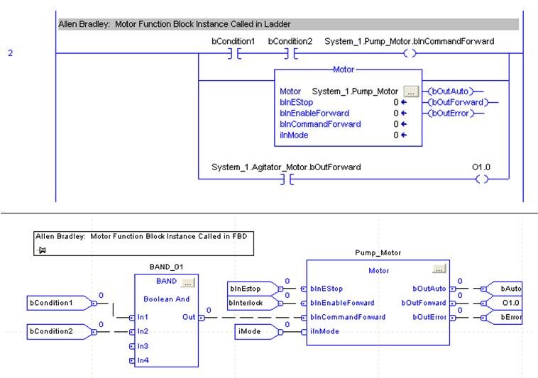
In AB:  Parameters in ladder have to be referenced independently from the function block call
If the function block instance is called in ladder, the input parameters can only be assigned with the block call if they are constants.  Variable inputs must be assigned to input parameters in preceding ladder rungs.  Outputs must be referenced in ladder rungs following the function block call.  If calling the function block instance in FBD (function block diagram), then variables can be directly assigned to input and output parameters.
Disadvantage:  More rungs of ladder to maintain.  If called in FBD instead, then there are restrictions on instance declaration (see below) and simple Boolean logic is more complicated because you must use the FBD function boxes instead of contacts and coils.

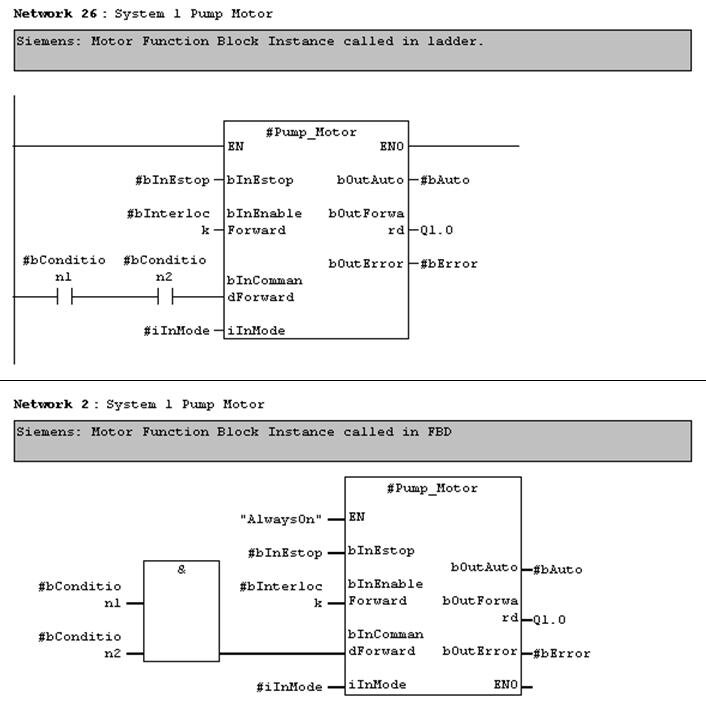
In Siemens:  Parameters are directly interfaced in both ladder and FBD
Function block instances that are called in ladder and FBD are essentially the same.  Even in ladder, variables can be assigned directly to input parameters.  Boolean input parameters can also be assigned to the result of ladder logic operations.  Function block outputs can be assigned directly to variables in the same rung of ladder.
Note that function block input and output parameters can also be accessed symbolically from other rungs in ladder logic (just like the AB example above), but Siemens has the additional advantage of directly assigning input and output parameters in the same rung as the function block call.
Advantage:  All input and output parameter assignment for a function block instance can be consolidated in one rung and not spread out on separate rungs or throughout the program.

Declaring an instance of a function block

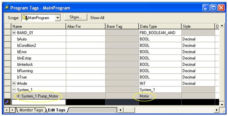
In AB:  Limited to program tag file.  If using FBD, cannot reside in a UDT
Instances of AOIs are most commonly declared in the “Program Tags” file of a program folder.   Even for very modular programs, all function blocks are listed in this one common location.  Instances can be declared within UDTs (user-defined types), but not if you want to use them in the FBD environment.
Advantage:  Simplicity.  One location to look through for each program folder.

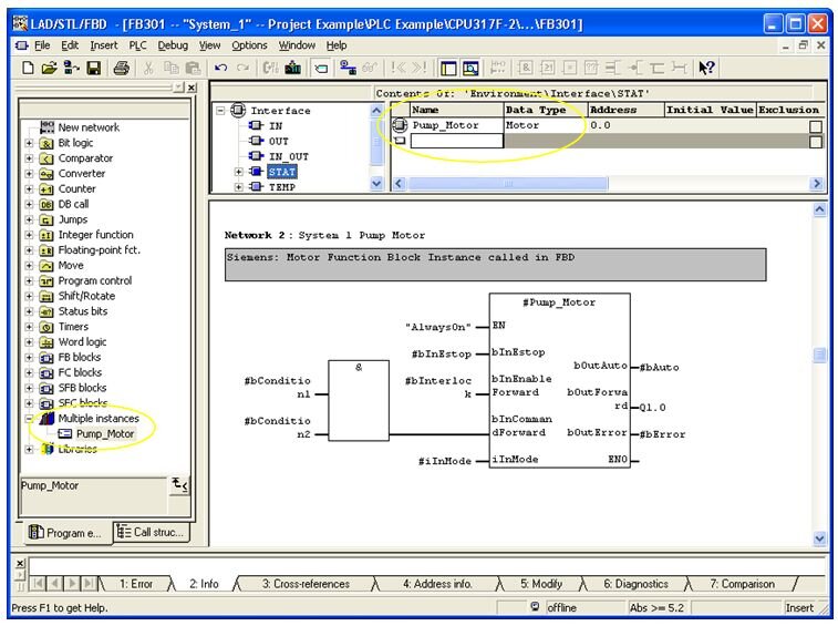
In Siemens:  Memory resides in an instance data block, but is declared within parent function blocks.
Most program logic, not just reusable logic, is located within function blocks.  “Parent” function blocks are assigned an instance data block.  All reusable function block instances can be declared within the parent function block’s static memory.
Advantage:  Modularity.  Instances are declared within the function block that they are called.

Summary 

In summary, Siemens seems to offer a little more flexibility in how function blocks are interfaced and instantiated.  We have seen, however, that both Allen Bradley and Siemens offer solutions for reusable function blocks on their higher-end PLCs.  Both Function Blocks in Siemens and Add-On Instructions in Allen Bradley will enhance the modularity and maintainability of your PLC program.  
#