No Copy


No Right Click

Selamat Datang di Situs Belajar PLC dan SCADA

Blog gratis yang menyajikan berita seputar PLC dan SCADA.

Microsoft Windows 10

Berita seputar Microsoft Windows 10. Membahas berbagai informasi mengenai Microsoft windows terbaru.

Apple OSX

Artikel yang membahas tentang OSX terbaru dari Apple tentu sangat menarik untuk dibaca. Tak kalah serunya jika kita paham mengenai tips dan trik yang ada didalamnya.

Photography

Photography asik dan menarik jika kita mengetahuinya lebih dalam. Disini kita bisa melihat berbagai hal dari sudut pandang photo. Menarik untuk dipahami.

Thursday, December 11, 2008

Buku - Project Management

Project Managementreviews the steps in organizing and managing projects, from how to build a realistic schedule to how to measure both success and failure. A concise and accessible, yet authoritative, guide to a topic in which books are more often lengthy and technical,Project Managementdiscusses team building, timing, the planning process, estimating project costs, managing project interfaces, the four stages of risk management, and more.

Buku ini sangat bagus dan cocok bagi Project Manager.


Rincian lebih lanjut

Project Management
Oleh Gary Heerkens
Diterbitkan oleh McGraw-Hill Professional, 2001
ISBN 0071379525, 9780071379526
250 halaman

Mengenal Software terbaru Wonderware Intouch V 10.

InTouch menyediakan perangkat lunak grafis visualisasi yang akan membawa Anda operasi manajemen, kontrol dan optimasi ke tingkat yang sama sekali baru. InTouch HMI reputasi yang berdiri di atas semuanya. 

Industri tahu, sebagai Human Machine Interface (HMI) semuanya dimulai dengan perangkat lunak InTouch lebih dari dua puluh tahun yang lalu. Tidak lain HMI, InTouch cocok dengan perangkat lunak untuk industri terkemuka yang memerlukan inovasi, arsitektur integritas, unequaled perangkat integrasi dan konektivitas, migrasi perangkat lunak, dan benar-benar legendaris mudah digunakan. 

Click to view larger image 

Semua ini juga dirancang untuk memimpin-standar sistem yang didorong memaksimalkan produktivitas, penggunaaanya  mengoptimalkan efektivitas, peningkatan mutu, dan ekonomis dalam pemeliharaan, dan biaya operasional untuk membantu Anda membuat perusahaan terbaik.

Kunci Manfaat:
  1. Benar-benar legendaris mudah-guna memungkinkan pengembang dan operator dengan cepat dan mudah untuk lebih produktif.
  2. Unequaled perangkat integrasi dan konektivitas untuk hampir setiap perangkat dan sistem.
  3. Ruangan grafis visual perwakilan dan interaksi dengan operasi membawa informasi yang tepat untuk orang yang tepat pada waktu yang tepat.
  4. Sejarah migrasi tanpa gangguan perangkat lunak versi jalan yang berarti Anda HMI aplikasi investasi dilindungi.
Kemampuan:
  1. Resolusi gambar independen dan cerdas simbol visual yang membawa Anda fasilitas untuk kehidupan di kanan layar komputer Anda.
  2. Script canggih untuk memperpanjang dan menyesuaikan aplikasi untuk kebutuhan khusus Anda.
  3. Real-time didistribusikan dengan sejarah sering dilihat untuk analisis .
  4. Built-in, real-time dan sejarah Tren.
  5. Microsoft dan kontrol ActiveX. NET kontrol integrasi.
  6. Extensible database icon lebih dari 500 pra-dirancang 'cerdas' dan disesuaikan objek grafis dan simbol.

Wednesday, December 10, 2008

Buku Pegangan untuk Electrical dan Automatioin Engineer

Berikut ini saya lampirkan buku gratis yang bisa anda download. Buku ini merupakan teori dasar untuk Electrical Engineer dan Automation Engineer. Silahkan Klik di links berikut ini:

  1. Apa itu SCADA? Klik Disini!
  2. Basic of PLC Siemens Klik Disini!
  3. Basic of Electricity Klik Disini!
  4. Beginner Guide for PLC OMRON Klik Disini!
  5. CX Programmer -  Contoh Pemogramman Klik Disini!
  6. Electric Motors Basic Klik Disini!
  7. Electrical and Electronic Principles & Technology Klik Disini!
  8. Buku petunjuk Motor Listrik & Starter Klik Disini!
  9. PLC Handbook Klik Disini!
  10. Merancang Power Plant Klik Disini!
  11. Cara Menginstall RSLinx (Rockwell) Klik Disini!

Buku ini saya posting di www.4shared.com untuk memudahkan anda mendownloadnya. 

Selamat mendownload dan selamat membaca, semoga bermanfaat.

Friday, December 5, 2008

Persentasi Software Baru RSLOGIX5000 V17

Berikut ini persentasi mengenai software terbaru dari Rockwell RSLogix5000 V17. Semoga bermanfaat.


Jika ingin melihat lebih jelas silahkan klik http://docs.google.com/Presentation?id=dcsqcp9z_198tfnfqkdr

Wednesday, October 29, 2008

Advanced Project Management Oleh Harold Kerzner


Authoritative strategies for implementing project management Senior managers at world-class corporations open their office doors to discuss case studies that demonstrate their thought processes and actual strategies that helped them lead their companies to excellence in project management in less than six years! Following the Project Management Institute's Body of Knowledge (PMBOK ® ), industry leaders address: Project risk management Project portfolio management The Project Office Project management multinational cultures Integrated project teams and virtual project teams

Rincian lebih lanjut

Advanced Project Management: Best Practices on Implementation
Oleh Harold Kerzner
Diterbitkan oleh John Wiley and Sons, 2004
ISBN 0471472840, 9780471472841
847 halaman

BACA? KLIK DISINI!

Programmable Logic Controllers Oleh W. Bolton


This is the introduction to PLCs for which baffled students, technicians and managers have been waiting. In this straightforward, easy-to-read guide, Bill Bolton has kept the jargon to a minimum, considered all the programming methods in the standard IEC 1131-3 - in particular ladder programming, and presented the subject in a way that is not device specific to ensure maximum applicability to courses in electronics and control systems.

Now in its fourth edition, this best-selling text has been expanded with increased coverage of industrial systems and PLCs and more consideration has been given to IEC 1131-3 and all the programming methods in the standard. The new edition brings the book fully up to date with the current developments in PLCs, describing new and important applications such as PLC use in communications (e.g. Ethernet an extremely popular system), and safety in particular proprietary emergency stop relays (now appearing in practically every PLC based system).

The coverage of commonly used PLCs has been increased, including the ever popular Allen Bradley PLCs, making this book an essential source of information both for professionals wishing to update their knowledge, as well as students who require a straight forward introduction to this area of control engineering.

Having read this book, readers will be able to:
* Identify the main design characteristics and internal architecture of PLCs
* Describe and identify the characteristics of commonly used input and output devices
* Explain the processing of inputs and outputs of PLCs
* Describe communication links involved with control systems
* Develop ladder programs for the logic functions AND, OR, NOT, NAND, NOT and XOR
* Develop functional block, instruction list, structured text and sequential function chart programs
* Develop programs using internal relays, timers, counters, shift registers, sequencers and data handling
* Identify safety issues with PLC systems
* Identify methods used for fault diagnosis, testing and debugging programs

Fully matched to the requirements of BTEC Higher Nationals, students are able to check their learning and understanding as they work through the text using the Problems section at the end of each chapter. Complete answers are provided in the back of the book.

* Thoroughly practical introduction to PLC use and application - not device specific, ensuring relevance to a wide range of courses
* New edition expanded with increased coverage of IEC 1131-3, industrial control scenarios and communications - an important aspect of PLC use
* Problems included at the end of each chapter, with a complete set of answers given at the back of the book

Rincian lebih lanjut

Programmable Logic Controllers: an introduction
Oleh W. Bolton
Diterbitkan oleh Newnes, 2006
ISBN 0750681128, 9780750681124
304 halaman

Baca? Klik DISINI!

Instrument Engineer's Handbook


Bela Liptak's acclaimed "bible" of instrument engineering now enters its fourth edition with fully globalized coverage, an outstanding panel of international contributors, and major additional coverage that reflects the advances made over the last decade since publication of the third edition. Expanded coverage includes descriptions of overseas manufacturer's products and concepts, model-based optimization in control theory, new major inventions and innovations in control valves, and a full chapter devoted to safety. The book also covers the transmitters, controllers, valves, regulators, actuators, dampers, and other drives that have been introduced since the previous edition.

Rincian lebih lanjut

Instrument Engineers' Handbook: Process Control and Optimization
Oleh Bela G. Liptak
Diterbitkan oleh CRC Press, 2005
ISBN 0849310814, 9780849310812
2464 halaman

BACA? Klik Disini!

Buku Untuk ELECTRICAL ENGINEERING


Most books on transmission and distribution electrical engineering are student texts that focus on theory, brief overviews, or specialised monographs. Colin Bayliss and Brian Hardy have produced a unique and comprehensive handbook aimed squarely at the engineers and planners involved in all aspects of getting electricity from the power plant to the user via the power grid. The unique scope of this book embraces power systems, substations, cabling, switchgear, power systems protection, overhead lines, project management, planning, regulations, and more... The third edition include a new chapter on power quality, a thoroughly updated section on earthing and bonding, coverage of the integration embedded generation and renewables in modern power systems, and has been fully updated in line with the latest IEC and European standards. The resulting book is an essential read, and a hard-working reference for all engineers, technicians, managers and planners involved in electricity utilities, and related areas such as generation, and industrial electricity usage. 1. A reference handbook written by engineers for engineers 2. Unrivalled in its scope, covering systems, substations, cabling, switchgear, power systems protection, overhead lines, project management, planning, regulations, and more... 3. The third edition includes expanded sections on power quality, a thoroughly updated section on earthing and bonding, and coverage of the integration embedded generation and renewables in modern power systems

Rincian lebih lanjut

Transmission And Distribution Electrical Engineering: Electrical Engineering
Oleh C. R. Bayliss, B. J. Hardy
Kontributor C. R. Bayliss, B. J. Hardy
Diterbitkan oleh Newnes, 2006
ISBN 0750666730, 9780750666732
1010 halaman

BACA ? Klik Disini!

-------------------------------------


Practical TCP/IP and Ethernet Networking


TCP/IP (Transmission Control Protocol/Internet Protocol) is the suite of communications protocols used to connect hosts on the Internet. TCP/IP uses several protocols, the two main ones being TCP and IP. TCP/IP is built into the UNIX operating system and is used by the Internet, making it the de facto standard for transmitting data over networks. The TCP/IP suite of protocols has become a dominant technology due to its widespread use and reliability, while Ethernet is fast becoming a de facto industrial networking standard.

Rincian lebih lanjut

Practical TCP/IP and Ethernet Networking
Oleh Deon Reynders, Edwin Wright
Diterbitkan oleh Newnes, 2003
ISBN 0750658061, 9780750658065
306 halaman

Silahkan KLIK DISINI! untuk membaca bukunya.

Practical Modern SCADA Protocols

Satu lagi buku yang membahas total tentang SCADA. Anda bisa menemukannya disini.

Yang berminat silahkan KLIK DISINI!

Anda bisa membacanya atau mendownloadnya.

Buku “Practical - SCADA For Industry”

Kepengen belajar tentang SCADA? Ada baiknya sahabat download buku ini SCADA (Supervisory Control and Data Acquisition) For Industry Klik Disini.

Buku ini berisikan 298 halaman. Berikut ini daftar isi dari buku tersebut:

1 Background to SCADA 1
1.1 Introduction and brief history of SCADA 1
1.2 Fundamental principles of modern SCADA systems 2
1.3 SCADA hardware 4
1.4 SCADA software 5
1.5 Landlines for SCADA 6
1.6 SCADA and local area networks 7
1.7 Modem use in SCADA systems 7
1.8 Computer sites and troubleshooting 8
1.9 System implementation 9
2 SCADA systems, hardware and firmware 11
2.1 Introduction 11
2.2 Comparison of the terms SCADA, DCS, PLC and smart instrument 12
2.2.1 SCADA system 12
2.2.2 Distributed control system (DCS) 15
2.2.3 Programmable logic controller (PLC) 15
2.2.4 Smart instrument 16
2.2.5 Considerations and benefits of SCADA system 17
2.3 Remote terminal units 17
2.3.1 Control processor (or CPU) 19
2.3.2 Analog input modules 19
2.3.3 Typical analog input modules 26
2.3.4 Analog outputs 27
2.3.5 Digital inputs 28
2.3.6 Counter or accumulator digital inputs 29
2.3.7 Digital output module 31
2.3.8 Mixed analog and digital modules 33
2.3.9 Communication interfaces 33
2.3.10 Power supply module for RTU 33
2.3.11 RTU environmental enclosures 33
2.3.12 Testing and maintenance 34
2.3.13 Typical requirements for an RTU system 35
2.4 Application programs 36
2.5 PLCs used as RTUs 36
2.5.1 PLC software 37
2.5.2 Basic rules of ladder-logic 38
2.5.3 The different ladder-logic instructions 40
2.6 The master station 46
2.6.1 Master station software 48
vi Contents
2.6.2 System SCADA software 48
2.6.3 Local area networks 48
2.6.4 Ethernet 49
2.6.5 Token ring LANs 51
2.6.6 Token bus network 52
2.7 System reliability and availability 52
2.7.1 Redundant master station configuration 52
2.8 Communication architectures and philosophies 54
2.8.1 Communication architectures 54
2.8.2 Communication philosophies 56
2.8.3 Polled (or master slave) 56
2.8.4 CSMA/CD system (peer-to-peer) 59
2.9 Typical considerations in configuration of a master station 61
3 SCADA systems software and protocols 64
3.1 Introduction 64
3.2 The components of a SCADA system 64
3.2.1 SCADA key features 65
3.3 The SCADA software package 67
3.3.1 Redundancy 70
3.3.2 System response time 72
3.3.3 Expandability of the system 72
3.4 Specialized SCADA protocols 72
3.4.1 Introduction to protocols 73
3.4.2 Information transfer 74
3.4.3 High level data link control (HDLC) protocol 78
3.4.4 The CSMA/CD protocol format 80
3.4.5 Standards activities 81
3.5 Error detection 82
3.5.1 Causes of errors 83
3.5.2 Feedback error control 84
3.6 Distributed network protocol 87
3.6.1 Introduction 87
3.6.2 Interoperability 87
3.6.3 Open standard 87
3.6.4 IEC and IEEE 88
3.6.5 SCADA 88
3.6.6 Development 88
3.6.7 Physical layer 88
3.6.8 Physical topologies 88
3.6.9 Modes 89
3.6.10 Datalink layer 92
3.6.11 Transport layer (pseudo-transport) 96
3.6.12 Application layer 97
Contents vii
3.6.13 Conclusion 97
3.7 New technologies in SCADA systems 97
3.7.1 Rapid improvement in LAN technology for master stations 97
3.7.2 Man machine interface 97
3.7.3 Remote terminal units 98
3.7.4 Communications 98
3.8 The twelve golden rules 98
4 Landlines 100
4.1 Introduction 100
4.2 Background to cables 100
4.3 Definition of interference and noise on cables 101
4.4 Sources of interference and noise on cables 102
4.4.1 Electrostatic coupling 103
4.4.2 Magnetic coupling 104
4.4.3 Impedance coupling 105
4.5 Practical methods of reducing noise and interference on cables 107
4.5.1 Shielding and twisting wires 107
4.5.2 Cable spacing 108
4.5.3 Tray spacing 110
4.5.4 Earthing and grounding requirements 111
4.5.5 Specific areas to focus on 111
4.6 Types of cables 112
4.6.1 General cable characteristics 112
4.6.2 Two wire open lines 114
4.6.3 Twisted pair cables 114
4.6.4 Coaxial cables 116
4.6.5 Fiber optics 116
4.6.6 Theory of operation 116
4.6.7 Modes of propagation 118
4.6.8 Specification of cables 120
4.6.9 Joining cables 120
4.6.10 Limitations of cables 121
4.7 Privately owned cables 121
4.7.1 Telephone quality cables 121
4.7.2 Data quality twisted pair cables 122
4.7.3 Local area networks (LANs) 122
4.7.4 Multiplexers (bandwidth managers) 122
4.7.5 Assessment of existing copper cables 125
4.8 Public network provided services 125
4.9 Switched telephone lines 126
4.9.1 General 126
4.9.2 Technical details 126
4.9.3 DC pulses 128
viii Contents
4.9.4 Dual tone multifrequency — DTMF 128
4.10 Analog tie lines 128
4.10.1 Introduction 128
4.10.2 Four wire E&M tie lines 129
4.10.3 Two wire signaling tie line 130
4.10.4 Four wire direct tie lines 131
4.10.5 Two wire direct tie lines 131
4.11 Analog data services 131
4.11.1 Introduction 132
4.11.2 Point-to-point configuration 132
4.11.3 Point-to-multipoint 132
4.11.4 Digital multipoint 133
4.11.5 Switched network DATEL service 134
4.11.6 Dedicated line DATEL service 134
4.11.7 Additional information 135
4.12 Digital data services 135
4.12.1 General 135
4.12.2 Service details 135
4.13 Packet switched services 136
4.13.1 Introduction 136
4.13.2 X.25 service 138
4.13.3 X.28 services 138
4.13.4 X.32 services 139
4.13.5 Frame relay 139
4.14 ISDN 139
4.15 ATM 141
5 Local area network systems 142
5.1 Introduction 142
5.2 Network topologies 143
5.2.1 Bus topology 143
5.2.2 Bus topology advantages 144
5.2.3 Bus topology disadvantages 144
5.2.4 Star topology 144
5.2.5 Ring topology 145
5.3 Media access methods 146
5.3.1 Contention systems 146
5.3.2 Token passing 147
5.4 IEEE 802.3 Ethernet 147
5.4.1 Ethernet types 148
5.4.2 10Base5 systems 148
5.4.3 10Base2 systems 150
5.4.4 10BaseT 151
5.4.5 10BaseF 153
Contents ix
5.4.6 10Broad36 153
5.4.7 1Base5 153
5.4.8 Collisions 153
5.5 MAC frame format 154
5.6 High-speed Ethernet systems 155
5.6.1 Cabling limitations 155
5.7 100Base-T (100Base-TX, T4, FX, T2) 156
5.7.1 Fast Ethernet overview 156
5.7.2 100Base-TX and FX 157
5.7.3 100BASE-T4 157
5.7.4 100Base-T2 158
5.7.5 100Base-T hubs 158
5.7.6 100Base-T adapters 159
5.8 Fast Ethernet design considerations 159
5.8.1 UTP Cabling distances 100Base-TX/T4 159
5.8.2 Fiber optic cable distances 100Base-FX 159
5.8.3 100Base-T repeater rules 160
5.9 Gigabit Ethernet 1000Base-T 160
5.9.1 Gigabit Ethernet summary 160
5.9.2 Gigabit Ethernet MAC layer 161
5.9.3 1000Base-SX for horizontal fiber 162
5.9.4 1000Base-LX for vertical backbone cabling 163
5.9.5 1000Base-CX for copper cabling 163
5.9.6 1000Base-T for category 5 UTP 163
5.9.7 Gigabit Ethernet full-duplex repeaters 163
5.10 Network interconnection components 164
5.10.1 Repeaters 164
5.10.2 Bridges 165
5.10.3 Router 165
5.10.4 Gateways 166
5.10.5 Hubs 166
5.10.6 Switches 167
5.11 TCP/IP protocols 169
5.11.1 The TCP/IP protocol structure 170
5.11.2 Routing in an Internet 170
5.11.3 Transmission control protocol (TCP) 171
5.12 SCADA and the Internet 172
5.12.1 Use of the Internet for SCADA systems 173
5.12.2 Thin client solutions 173
5.12.3 Security concerns 174
5.12.4 Other issues 175
5.12.5 Conclusion 175
x Contents
6 Modems 176
6.1 Introduction 176
6.2 Review of the modem 176
6.2.1 Synchronous or asynchronous 178
6.2.2 Modes of operation 179
6.2.3 Components of a modem 180
6.2.4 Modem receiver 180
6.2.5 Modem transmitter 181
6.3 The RS-232/RS-422/RS-485 interface standards 182
6.3.1 The RS-232-C interface standard for serial data communication 182
6.3.2 Electrical signal characteristics 183
6.3.3 Interface mechanical characteristics 185
6.3.4 Functional description of the interchange circuits 185
6.3.5 The sequence of asynchronous operation of the RS-232 interface 186
6.3.6 Synchronous communications 187
6.3.7 Disadvantages of the RS-232 standard 188
6.3.8 The RS-422 interface standard for serial data communications 188
6.3.9 The RS-485 interface standard for serial data communications 190
6.4 Flow control 191
6.5 Modulation techniques 191
6.5.1 Amplitude modulation (or amplitude shift keying) 192
6.5.2 Frequency modulation (or frequency shift keying — FSK) 192
6.5.3 Phase modulation (or phase shift keying (PSK)) 192
6.5.4 Quadrature amplitude modulation (or QAM) 193
6.5.5 Trellis coding 194
6.5.6 DFM (direct frequency modulation) 195
6.6 Error detection/correction and data compression 196
6.6.1 MNP protocol classes 196
6.6.2 Link access protocol modem (LAP-M) 197
6.6.3 Data compression techniques 198
6.7 Data rate versus baud rate 201
6.8 Modem standards 202
6.9 Radio modems 203
6.10 Troubleshooting the system 207
6.10.1 Troubleshooting the serial link 207
6.10.2 The breakout box 208
6.10.3 Protocol analyzer 208
6.10.4 Troubleshooting the modem 209
6.11 Selection considerations 210
7 Central site computer facilities 212
7.1 Introduction 212
7.2 Recommended installation practice 212
7.2.1 Environmental considerations 212
Contents xi
7.2.2 Earthing and shielding 213
7.2.3 Cabling 213
7.2.4 Power connections 214
7.3 Ergonomic requirements 215
7.3.1 Typical control room layout 215
7.3.2 Lighting 216
7.3.3 Sound environment 216
7.3.4 Ventilation 216
7.3.5 Colors of equipment 217
7.4 Design of the computer displays 217
7.4.1 Operator displays and graphics 218
7.4.2 Design of screens 219
7.5 Alarming and reporting philosophies 220
8 Troubleshooting and maintenance 223
8.1 Introduction 223
8.2 Troubleshooting the telemetry system 225
8.2.1 The RTU and component modules 225
8.2.2 The master sites 227
8.2.3 The central site 227
8.2.4 The operator station and software 227
8.3 Maintenance tasks 228
8.4 The maintenance unit system 230
9 Specification of systems 232
9.1 Introduction 232
9.2 Common pitfalls 232
9.3 Standards 233
9.4 Performance criteria 233
9.5 Testing 233
9.6 Documentation 234
9.7 Future trends in technology 234
9.7.1 Software based instrumentation 234
9.7.2 Future trends in SCADA systems 235

Selamat Mendownload dan Selamat Membaca….

DOWNLOAD: Klik Disini.

Thursday, October 16, 2008

Tutorial Singkat RSEmulator 5000

Untuk membaca lebih lengkap mengenai RSEmulator 5000. Silahkan Klik DISINI!

Tahukah anda, Apakah RSEmulator 5000?

RSEmulator 5000 adalah software yang dikeluarkan oleh Rockwell Automation untuk Simulasi PLC menggunakan software (internal PC). Software ini dilink dengan RSLogix 5000 menggunakan RSLinx.

Untuk jelasnya mendingan baca deh ..... Silahkan Klik DISINI!

Dibawah ini sedikit informasi mengenai RSEmulator.

--------------------
RSlogix Emulate 5000 ReadMe.txt File, 20-JAN-2007

*******************************************************
*WARNING: Do not depend on the emulator to match your *
*physical controller’s performance or operation. Some *
*instructions are interpreted differently in the *
*emulator than in a physical controller, and the *
*execution times for instructions and program files *
*will be significantly different in an emulated *
*controller than in a physical controller. *
*******************************************************

This readme file contains information on the following:
* System Requirements
* Product Revision Information
* Installation Procedure
* Technical Information
* Contact Information


System Requirements
Base Platform Requirements:
Intel Pentium 4 1.6GHz (single core, dual-core, and hyperthreaded CPUs are supported)
A minimum of 256 Mb of RAM
150 Mb of hard disk space free
800 X 600 video resolution
Any Windows-compatible pointing device

Operating System:
Microsoft Windows 2000 with Service Pack 4 (recommended)
Microsoft Windows XP with Service Pack 1 or higher (recommended)
Microsoft Windows 2003 Server

Product Revision Information
RSLogix Emulate 5000 Version 16.00.00 requires the following:

Software Product Compatible Versions:
RSLinx 2.51.00 or higher
Any RSLogix 5000 version from Version 12 through 16


Installation Procedure
Product Installation:
Begin the installation of the product by running the setup.exe file
located at the root of the CD media. This will launch a CD browser that
provides a means to install the RSLogix Emulate 5000 product, and
also displays pertinent product information.

Please use the "Add/Remove Programs" applet in control panel to remove
previous versions of SoftLogix5800. While performing an install or uninstall,
please note any messages that recommend a system reboot. Failure to follow
the reboot instructions can render your installation inoperable.

If you want to reinstall the same vesion as is currently installed, please use the
"Add/Remove Programs" applet in control panel to remove the existing version of
RSLogix Emulate 5000. While performing an install or uninstall, please note any
messages that recommend a system reboot. Failure to follow the reboot instructions
can render your installation inoperable.

Please refer to the RSLogix Emulate 5000 Getting Results Guide for details on
installing this product. This document can be viewed with the Adobe Acrobat
Reader by opening the file LGEM5K-GR016A-EN-P.pdf located at
\Documentation on the RSLogix Emulate 5000 CD.

IMPORTANT NOTES:
RSLogix Emulate 5000 cannot be installed on any machine that already has
SoftLogix5800 installed on it.

RSLinx Classic should be installed before installing the RSLogix Emulate 5000
product.

If RSLinx Classic is installed after RSLogix Emulate 5000, please run the
SIRegEDS.exe program that can be found in the RSEMU5000 directory on the
installation CD. After the products are installed, you must first add the
Virtual Backplane driver in RSLinx Classic in order to connect to the
SoftLogix engine.

Even if you plan to remotely program the controller over a ControlNet or
Ethernet link, you must add the Virtual Backplane driver via RSLinx Classic
software. If you do not, persistent storage will not function and when you
reboot the computer, the controller will come up with cleared memory (the
program will not get re-loaded).

Data Execution Prevention (a feature of Microsoft Windows also known as DEP) is
not supported by RSLogix Emulate 5000. If your computer's CPU supports DEP, we
advise using DEP for only essential Windows programs and services. (This is the
default setting for Windows XP; for Windows Server 2003, DEP is on by default
for all programs and services.) If DEP is turned on for RSLogix Emulate 5000,
you may experience unexpected results. See your Windows documentation for
information regarding DEP.

Jump to Subroutine (JSR) instructions do execute in the emulator. However,
the instruction passes parameters to subroutines in reverse order from the
order in a physical controller (the last parameter is passed first in an
emulated controller). Do not use JSR instructions in a manner where the
order in which parameters are passed to a subroutine matters.

Technical Information
Refer to the RSLogix Emulate 5000 Getting Results Guide for more information about using
this product. This document can be viewed with the Adobe Acrobat Reader by opening the
file LGEM5K-GR016A-EN-P.pdf located at \Documentation on the RSLogix
Emulate 5000 CD.


Contact Information
If you have any problems installing or running this software, please contact:

Rockwell Automation Technical Support
Phone: 440-646-5800
WEB: support.rockwellautomation.com

Cara Setup OPC dengan Simatic Net

Tahukah anda, bagaimana cara men-setup OPC dengan menggunakan Simatic NET?

Pengen Tahu? Silahkan cek ling berikut ini. Klik Disini!

Tuesday, October 14, 2008

Statement List (STL) Cheat Sheets

If you are a Siemens PLC user then you've more then likely have run into Statement List (STL) programming. STL corresponds to the Instruction List language defined in the IEC 61131-3 specification. The programming is done with very simple mnemonics that can be hard to remember if you don't use it very often.

These cheat sheets provide a quick reference guide for all the instructions and formatting. They are two pages long but if you can print on the front and back then they make for a nice one sheet reference.

STL Listed Alphabetically

Best used when trying to interpret an existing program.

Download: PDF (131KB)

STL Listed by Category

Download : PDF

Case Study: Bronco Wine Company

Courtesy of: Inductive Automation

Weaving it all together with Web Technology

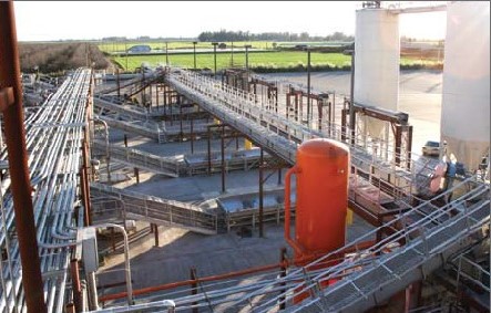
Bronco Wine Company, Ceres, CA (the producer of “Two-buck Chuck”) uses FactoryPMI for enterprisewide process monitoring, control, and troubleshooting. It was a business decision to use this technology, and is paying off handsomely for the Franzia family-owned business.

Bronco Winery — Who are they?

“Bronco Winery is passionate about producing its wines with a consistent color, flavor, and ‘mouth-feel’”, says John Franzia, a co-owner in the California-based Bronco Wine Company. He is also a 60-something embracer of technology. He comments “Anytime, everywhere”—referring to his company’s adoption of Inductive Automation’s FactoryPMI Plant Management software solution to help his staff run their wine business.

The metrics are staggering. Their top brand—Charles Shaw— sells for $2 in California, and is known as “2-Buck-Chuck”. They produce and ship over 45 million liters or 12 million gallons of this brand annually.

Other wineries that use Bronco’s services require rigorous testing and process validation since it is THEIR reputations on the line. Bronco, with facilities in Ceres, Escalon, Napa, and Sonoma can manage this and all sides of their business because of the processes they have put into place.

“FactoryPMI is an integral part of our success,” suggests Bob Stashak, winemaker at Bronco’s Domaine Napa winery. “Our reputation is at stake.”

Bronco Wine Company

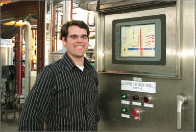
Meet Paul Franzia, Engineering Manager

“We are growers, producers, blenders, bottlers, and exporters of wine.” This suggests that the complex processes and procedures of winemaking have to be right.

“We are growing all the time,” he says.

He is responsible for the move to FactoryPMI. “We were using a SCADA product for environmental controls, and interfacing it [HMI] with the PLCs that were doing the control,” says Franzia. “Communication was sporadic, and was frequently non-responsive,” he mentions.

As the need to bring more information to more people grew, it was obvious that Bronco had a problem.

“They wanted big dough to re-license each existing client,” lamented Franzia. “FactoryPMI doesn’t use this model.” It is estimated that Bronco saved over $300,000 on client licenses alone.

That wasn’t the only battle that Bronco was fighting. Their enterprise plant management and SCADA solution needed to integrate with the databases from other enterprise software applications (IFS Maintenance Management Software and ProPak). It needed to provide scalability for over 150 clients in their 4 locations, plus remote access for troubleshooting.

Project costs were important. The selected software had to be efficient in deployment of clients and development of applications due to the geography. When a new project came on-stream, everyone needed to have it—automatically. And when a new client was needed, or client access rights had to be modified, it needed to be done quickly. A web-deployed system using open standards would be desirable.

And with compliance issues of utmost importance, reporting in both real-time and historically was paramount!

With the multiple plants, Bronco also had a need for all people to see all things.

“We needed to upgrade.” Paul Franzia states.

Bronco chose FactoryPMI from Inductive Automation.

FactoryPMI is a database-centric enterprise-class plant management and SCADA software which is helping Bronco Winery streamline their business as well as helping them meet their production targets and the stringent compliance requirements of the wine industry.

FactoryPMI uses a web browser to launch its client interface. Any computer that can connect to the network and run a browser is a FactoryPMI client. All the user needs is a login ID, and they can access the system to the level which their login group allows them to go.

Administrators can add or delete users on the fly, in real-time— and from anywhere! The security model inherent in the software allows for administrators to fine tune the projects, set user policies and tracks the activities at every FactoryPMI client.

FactoryPMI uses an SQL database as its engine. Interacting and sharing information with different databases is one of the main design features behind FactoryPMI.

A full reporting tool for real-time and historical data was attractive to Bronco—especially the ‘Click-to-Graph’ component.

FactoryPMI is a solution for operations as well as the business, connecting the enterprise from the plant floor to the back office. Based on standard software platforms such as Java and OPC, FactoryPMI allows Bronco to implement Paul Franzia’s dream of having real-time insight into the operations for himself and his supervisors, and John Franzia’s desire to stay successful.

How FactoryPMI is Working for Bronco

Real-time? No problem. In the past, many of the operations were based on paper and telephone conversations. “I can be in Napa, and see what’s going on in Ceres right now. Sometimes, I tell the supervisor that there is a problem before he even knows. FactoryPMI has given us insight into our business,” Franzia states.

Phone calls from supervisors can come to Paul Franzia’s phone at any time. Regardless of where he is (even in his truck he can use his laptop and air card), he can log into the system, and onto the screen that his supervisor is looking at and provide instant ‘managerial’ feedback and help.

Management efficiency is bettered greatly.

“Manual operations are where the mistakes happen. We are removing those opportunities so they (the operators) can’t make mistakes.”

Supervisors need access to their area of responsibility from wherever they are. Ken Cullum, Maintenance Manager at the Ceres Winery says, “Our refrigeration guys would have to record the same data in four different places. Now they enter it at any FactoryPMI station.”

Inductive Automation Panel

Benefits to the Winemaking Process

The locations, although miles apart, need to appear on— screen as if they were under the same roof. FactoryPMI’s project redirection feature allows that to happen. There are presently six servers running FactoryPMI—four in Ceres, one in Escalon, and one in Napa. Each server has certain projects running on them. When a user needs to view a different part of the operation, the software redirects the client to the required project even if it’s on a different server.

Server clustering allows the FactoryPMI servers to be redundant. These servers can run the same projects, and in future state, the servers will be configured in a clustered environment which will provide redundancy.

Bronco blends wine for that consistent ‘mouth-feel’ that John Franzia talked about. The winemakers need historical data such as temperatures, and analytical data to determine which tank of wine to use for their current schedule.

Tank management is a huge part of a winemakers’ daily and weekly job description. FactoryPMI serves up the data to allow them to make the business decisions necessary to properly manage their raw assets.

If a tank temperature went too high, they will know, and will be able to adjust their procedures accordingly. Bronco is moving towards wireless tank gauging, which will be monitored by FactoryPMI. Reports and real-time alerts will be pushed to the managers and the winemakers automatically.

During crush [a 24/7 grape harvest season], the weather is king. Everything is subject to change, and when it does everyone needs to know now. When a winemaker changes the plan, the process has to be agile and react. Cross-shift information exchange is no longer a challenge for Bronco.

FactoryPMI interfaces with the ProPak ‘grower relations’ database. Trucks carrying grapes arrive at the winery, and the load is analyzed and data entered into ProPak. When the same truck arrives at the dump pit some time later, FactoryPMI interrogates the ProPak database, and compares the information with its own database, which has been manipulated by a winemaker.

During crush, there is no time for mistakes. “Our seasonal employees are not wine-wise,” says John Franzia. “They don’t know the difference between a zinfandel grape and a chardonnay, and these are the employees that are dumping the trucks.”

The right truck HAS to be dumped into the right pit, at the right time. If the wrong load gets dumped into the wrong pit, it could mean the loss of hundreds of thousands of dollars to Bronco for each occurrence.

Without manual intervention, the truck is only dumped if everything matches.

Benefits to the Bottling Operations

In all locations everyone knows ‘how you’re doing’ because of FactoryPMI. As Dino Rossini, Operations Manager suggests, “We produce a minimum of 20,000 cases a day here. This is our only KPI [Key Performance Indicator]. That’s the only thing that matters, and no one can fool the system.”

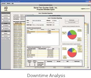
“The downtime analysis from FactoryPMI gives me the ability to ‘predict’ failures based on my knowledge,” he says. “The login and security gives the operator ownership of the ’ whatever it is that he is about to do’.”

“The trending and relational data logging of PMI helps me out in a big way. The historical rear view mirror is especially helpful when we are trying to figure out a problem.”

“They can look at it, and they can do something about it!” exclaims John Franzia.

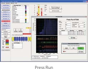
The Click-to-Graph function has been especially useful. “Click it and up it comes,” smiles Paul Franzia.

Robert Hall, Production Manager at the Ceres Winery adds, “We use FactoryPMI to track our efficiencies, and chart our downtime. It helps with line setups as well.”

Once the wine is bottled, the finished product is trucked to a climate controlled warehouse. Based on real-time and anticipated data from the weather service, FactoryPMI tells the PLC what to do. “This is where using Java makes things like this easy,” says Paul Fallgren, the chief integrator of the Bronco technology solution at Calmetrics. “We could not have done what Paul (Franzia) wanted to do with conventional software. FactoryPMI uses industry standard methods and practices which allows me to integrate our solution with all of the other technology that Bronco uses. The owner’s demands are high, and we can respond. Their needs can be easily met with FactoryPMI development timelines.”

Downtime Analysis Screen Press Run Screen

Reporting, Troubleshooting and Tech Support

“I’m the eye in the sky with FactoryPMI and all of the managers know it,” grins Paul Franzia. Using the graph trending, data logging tables and Click-to-Graph, Franzia can easily track and pin-point operational issues to solve problems in real time. The downtime reporting tools within FactoryPMI are really what he likes. “That’s the best,” he states very deliberately. The information that is gleaned from these reports has justified capital expenditure, and “made us better.” He was referring to hitting the production targets on a shift by shift basis. They rarely miss.

Rossini was very complimentary of Inductive Automation when it came to tech support. “We know who we’re dealing with, and can put a face on the company. They fix it.” This response was to the question of ‘What do you do when things don’t work as planned?’

Paul Franzia concurs. “We talk to the people who know, not a call center.”

John Franzia wraps up our conversation by saying, “We have a hell of a lot of stuff on it. It’s pretty impressive what the software can do.”

Paul Franzia is very matter of fact when he says that he can be in five places at once. “It makes me a better manager. Efficiencies have improved upwards of 30%, productivity targets are hit everyday, and I can be more responsive to the business and to my managers.”

Steve Hechtman, President of Inductive Automation has often said, “I am always looking for something that’s too good to be true.”

Bronco Winery has found it!

Connecting IFIX SCADA to Siemens S7 using TCP/IP

Setting up an S7 connection using TCP/IP

The TCP/IP method of communication to the S7-300 and S7-400 PLC's via TCP/IP communication module uses the S7WIN, S7WINSP, S7NT, or S7NTSP protocol.

Software requirements

  • Siemens SIMATIC NET software v6.1 SOFTNET-S7 Industrial Ethernet
  • IFIXSCADA v5.x or above
  • Windows XP + SP1

Hardware requirements

  • Standard network card
  • S7-300 with CPU315-2 DP
  • Siemens power supply PS30/5A
  • Siemens CP343-1 TCP

The hardware modules occupy the following slots in the Siemens PLC:

  1. Siemens power supply
  2. S7-300 CPU 315-2 DP
  3. Ethernet CP343-1 TCP

Example configuration

All wiring should be installed according to Siemens documentation.

Installing the SIMATIC NET software

You must log in as an Administrator to install the SIMATIC NET software. Close all other running applications, including any antivirus software you may be running.

  1. On the SIMATIC NET flash screen, start the installation by clicking Install SIMATIC NET Software.
  2. The PC configuration screen appears. Click Next.
  3. Select the English language option, then click Next. Click Next again.
  4. Click yes to the licensing agreement screen.
  5. Enter your Name and Company on the User Registration screen.
  6. If you already have SIMATIC NET software installed, this will be the drive selected by default. Clear the Run automatic authorization option, and then click next. The Setup: Configuration screen appears.
  7. Select all application options to be installed. (This is necessary if you do not already have STEP7 installed on your machine. If STEP7 v5.2 or higher is already installed, you do not have to select the NCM PC/S7 v5.2 application.) Click Next.
  8. The applications you selected are installed. At the prompt, click OK to restart your system. The system restarts and installs the selected applications. Click Finish to restart your system again.

The SIMATIC NET software is now installed.

Configuring the SIMATIC NET software

This step involves using the Commissioning Wizard to configure the software you installed in the previous step.

Configuring the module

When your system restarts after the software has been installed, your system's hardware configuration is scanned. The Commissioning Wizard appears automatically. (You can also access the Commissioning Wizard at Start/Simatic/SIMATIC NET/Settings/Commissioning Wizard.)

The number of steps required depends on the number of PC Ethernet cards (or modules) detected in your PC. The more modules you operate in the computer, the more steps are required.

  1. Click Next.

    An Ethernet Network Card with with the IP addresses settings shown above was found. This is the network card that will be configured for communication with the Siemens PLC. This is put on index 5.

    Note: The index of the network card can be set with the NCM PC Configuration (hardware configuration). The station index defaults to 5 if you use the Commissioning Wizard.

  2. Select the Use the module for productive operation in configured PC station option, and then click next.
  3. Clear the SIMATIC NET OPC Server in configured PC Station option and select the Configure more applications option. Then click next.
  4. Register the names for your user application: enter VFD1 in the Name text box. This user application is put on index 1. Click Next.

    Note: The name of the application is the VFD name. This comes later in the IFIX Project Editor under Communication | Ports in the Special options text box.
  5. Click Next. This screen appears, confirming you have completed configuring the module:
  6. The configuration is saved and the PC station is reconfigured. Your existing configuration data is overwritten. Click OK to confirm at the prompt.

This completes the module configuration.

Configuring the project with the PC Station Wizard

The next step to configure the project using the PC Station Wizard.

  1. Start the PC Station Wizard.
  2. Choose Create a new project and configuration. A new project is created. Click Next.
  3. Define a new Project name; this example uses IFIXS7. Specify where the copy of the local PC station settings resides, and then click Next.
  4. Select the Edit network and connection configuration option, and then click Finish. NetPro automatically starts, displaying the network configuration.
  5. Click the Application box in the PC station, and then choose Insert | New Connection. The Insert New Connection dialog box appears.
  6. Choose the Unspecified item in the tree. From the Type menu in the Connection area, choose S7 connection. Then click Apply, and then click OK.
  7. In the Properties -S7-Connection dialog box, the local IP Address should be the address of the Ethernet card in the PC. This example uses 192.168.0.190. The partner IP Address should be that of the Ethernet CP343 module in the PLC, in this case 192.168.0.148. The Local ID is the connection identifier of this connection (here it is S7-Connection_1). It will be used later on as the address of the IFIX I/O device. Click Address Details.

    Note: The Local ID S7-Connection_1 is used later in the IFIX Project Editor under Communication | I/O Devices in the I/O Device Address text box. This name is case-sensitive and cannot not contain any spaces.

  8. In the Address Details dialog box, enter the card location of the CPU that the SIMATIC S7 communicates with. Here the card location is 2. Click OK.

    Note: Some power supplies might occupy 2 slots. If so, the card location of the CPU is one higher at 3.

  9. In the NetPro window the new S7-Connection_1 connection appears. Choose Network | Save and Compile. The Save and Compile dialog box appears.
  10. Select the Compile and check everything option, and then click OK.
  11. After completing the save and compile operation, a message appears in the NetPro window. This indicates the warnings and errors present in the configuration. If warnings occur here, then this is to be handled as information only. But if errors occur, the project configuration cannot be loaded. To view errors, choose View |Outputs.
  12. Highlight by clicking on the PC Station (TESTXP). Afterwards the connection table disappears in the message window. From the NetPro menu choose PLC | Download | Selected Stations to transfer the project configuration to the PC. Alternatively, right-click the PC Station and choose Download | Selected Stations.
  13. To confirm the overwrite of configuration data and to proceed with the download, click Yes.
  14. To confirm stopping the Target Module (Network interface Card), click OK.
  15. The configuration should now be successfully loaded. Exit NetPro and click next, and next again to finish the Commissioning Wizard. If you have errors, see for details.

Defining an access point for the application

The next step is to define an access point for the application.

  1. The Configuration Console should appear after terminating the Commissioning Wizard. If it doesn't, open the Configuration Console by selecting START / SIMATIC / Simatic Net / Settings / Configuration Console.
  2. In the Configuration Console dialog box, right-click the Access Point object, and choose New | New access point.

    Note: You can choose any name for the Access point, but it cannot contain spaces and be longer than 32 characters.

  3. In the New access point dialog box, enter your access point name (this example uses IFIXS7). Select the hardware component that will be associated with this access point (TCP/IP -> ASUSTeK/Broadcom 440x in the example).

    Note: The access point name is used later in IFIXSCADA in the Project Editor under Communication | Boards in the Special Options text box. The access point name is case-sensitive.

    After creating the access point the Configuration Console should look like this:
  4. Close the Configuration Console.

This completes the Simatic NET software configuration.

Configuring the S7 driver

The IFIX S7 driver needs three names (settings) from the SIMATIC NET software
configuration. The following points are needed:

SIMATIC NET Configuration
example
IFIX Info
Access point of the application IFIXS7 Boards, Special options
Field
VFD/Application Name VFD1 Ports, Special options Field
Name of the connection (or Local
ID)
S7-Connection_1 IODevices, Address Field

Using the Express Wizard

You use the Express Wizard to configure your communications.

  1. In IFIX Explorer, create a new (empty) test project.
  2. In the IFIXSCADA Project Editor, choose Communication | Express Wizard.
  3. In the wizard:
    • Create a new I/O Servers e.g. IOServer.
    • Create a new I/O Device e.g. IODev.
    • Select external as the type of the I/O Device (PLC): Select the Siemens | S7-300 or S7-400| TCPIP using NE2000 network CARD for Windows NT for NT/W2K/XP/2003, or the TCPIP using NE2000 network CARD for Windows 95/98 for 95/98/ME option.
  4. Define the name of the connection. In this example it is S7-Connection_1.

    Note: Do not select the Link I/O Device to an external tag Database option.

This completes this section.

Setting the Access Point

The next step in the process is to set the access point of the application.

  1. Open the Boards dialog box by choosing Communication | Boards.
  2. In the Special Opt text box, enter the access point of the application. This example uses IFIXS7.

Setting the VFD name

The next step is to set the VFD name.

  1. Open the Ports dialog box by choosing Communication | Ports.
  2. In the Special Opt text box enter the VFD Name. In this case VFD1.

Checking the name of the S7 connection

The next step is to check the name of the S7 connection.

  1. Open the I/O Device dialog box by choosing Communication | I/O Devices.
  2. In the Address field enter the name of the connection to the PLC. This example uses S7-Connection_1.

Variable declaration

The next step is to declare the variables.

  1. Open the Tags Form by choosing Tags | Variable Tags.
  2. Create a variable with the following information:
    • Variable Tag Name: TestInteger
    • I/O Device Name: IODev
    • Type: INT
    • Address: DB190,0

Troubleshooting your S7 connection

Question: I receive the following error message when downloading the PC station in the SIMATIC NCM PC manager:

  • "The module "station manager" cannot be contacted. Change the on-line interface."
  • "For On-line connections via the PC internal interface a station name must be assigned in the component configurator. This name must be identical to the name of the PC station, as configured in the STEP7 (or Simatic Net) project."
  • "Online: No connection could be made. The participant does not announce itself."

Solution

  1. Check in SIMATIC NCM PC Manager under the Menu option Options | Set PG/PC Interface, whether the point of entrance S7ONLINE is linked with the PC internal (local) interface.
  2. The Station Configuration Editor tells you whether your module is Online. You can start the Station Configuration Editor by double-clicking the icon. This should not be OFFLINE, so to change its mode of operation, click Change Mode. The mode of operation should now change to ONLINE.
  3. Check the station name in the Station Configuration Editor. This must match with the name in SIMATIC NCM PC Manager. You can change the station name in the Station Configuration Editor by clicking Station Name.
  4. Open the Station Configuration Editor and the SIMATIC NCM PC Manager. Check the order and the number of configured components and the indexes that are used. These should match.

The Logix5000 Essential Manuals

The Allen Bradley Logix5000 family (ControlLogix, CompactLogix, FlexLogix, SoftLogix) has some very good manuals. If you are just starting out or need a refresher here are the key manuals and the order I would read them. If you have RSLogix 50000 installed then you will find some of these in the Help > Online Books menu. Revision 16 also has some great videos in the Learning Center.

The Basics

For starters there is the Quick Start manual.
manual Logix5000 Controllers Quick Start

If you don't deal with the PLCs or RSLogix 5000 too much and just need a quick reminder about the hardware or programming then the System Reference is perfect.
manual Logix5000 Controllers System Reference

The Essentials

If you are getting into programming and designing a system then you'll want to start off with the Common Procedure Manual. It has a lot of helpful examples dealing with all aspects of the system.
manual Logix5000 Controllers Common Procedures Programming Manual

Next comes the nitty gritty of each instruction. It's a good idea to at least peruse all the instructions so you have an idea of what is available.
manual Logix5000 Controllers General Instructions Reference Manual
manual Logix5000 Process Control and Drives Instructions Reference Manual
manual Logix5000 Controllers Motion Instructions
manual GuardLogix Safety Application Instruction Set Reference Manual

An often overlooked manual but filled with great information for getting the most out your designs is the Design Considerations Reference Manual. Certainly a must read if you are knee deep in the development and programming of Allen Bradley PLCs.
manual Logix5000 Controllers Design Considerations Reference Manual

Hardware Specifics

Specifics for the hardware can be found in the User Manuals and Installation Instructions for the PLC.

ControlLogix
manual ControlLogix System User Manual
manual ControlLogix Installation Instructions
manual ControlLogix Controller and Memory Board Installation Instructions

CompactLogix
manual CompactLogix System User Manual
manual CompactLogix 1769-L31 Installation Instructions
manual CompactLogix 1769-L32E, 1769-L35E Installation Instructions
manual CompactLogix 1769-L32C, 1769-L35CR Installation Instructions

FlexLogix
manual FlexLogix System User Manual
manual FlexLogix Controllers Installation Instructions

SoftLogix
manual SoftLogix System User Manual
manual SoftLogix Controllers Installation Instructions

GuardLogix
manual GuardLogix Controllers User Manual
manual GuardLogix Controllers Installation Instructions

Networking

If you are deciding on which network to use then see the Design Considerations manual and the section "Determine the Appropriate Network". Otherwise, for existing networks the following are helpful.

Ethernet/IP
manual Ethernet Design Considerations for Control System Networks
manual EtherNet/IP Modules in Logix5000 Control Systems User Manual
manual Guard I/O EtherNet/IP Safety Modules User Manual

ControlNet
manual ControlNet Modules in Logix5000 Control Systems

DeviceNet
manual DeviceNet Modules in Logix5000 Control Systems User Manual
manual Guard I/O DeviceNet Safety Modules

The links are from the AB site so they are the latest and greatest manuals. Let me know if any of them are broken or if I forgot one you think is essential.

A Quick Tutorial on RSLogix Emulator 5000

RSLogix Emulator 5000 is a software simulator for the Allen Bradley line of Logix 5000 controllers (ControlLogix®, CompactLogix®, FlexLogix®, SoftLogix5800® and DriveLogix®). The goal is to mimic the function of a PLC without the actual hardware and thus do advanced debugging. More information can be found in the AB publication LGEM5K-GR015A-EN-P.

As a quick introduction we’ll go through a simple example of setting up a simulation. This involves three major steps.

  1. Setting up the chassis monitor.
  2. Creating a connection in RSLinx.
  3. Creating a project with associated emulation hardware.

Setting up the Chassis Monitor

To start the Chassis Monitor, click Start > Programs > Rockwell Software > RSLogixEmulate 5000 > RSLogix Emulate 5000 Chassis Monitor.

RSEmulator 00 Open
When the emulator opens up you’re confronted with what looks like an empty chassis. In slot 0 is an RSLinx module which has to be there for the emulator communications to work. Your slot 1 might have another irremovable RSLinx module depending if you are running RSLogix Enterprise.
RSEmulator 01 - Empty Chassis Monitor

From here we set up our hardware configuration for simulation. Our first step will be to add the CPU. In this case it is a special one called an Emulation Controller.

  1. Click Slot > Create Module.
  2. Choose the Emulator RSLogix Emulate 5000 Controller.
  3. Chose slot 2 for the controller
  4. Click OK to add it to the chassis monitor.
    RSEmulator 02 Select Emulator Controller
  5. At this point you may be accosted with a message about previous configurations. Just select Reset the Configuration to Default Values and click NEXT.
  6. The next two dialog screens are for setting up the controller details. Click NEXT and FINISH to accept all the defaults.
    RSEmulator 03 Emulator Controller Setup 1
    RSEmulator 04 Emulator Controller Setup 2

Next we’ll add some input/output simulation.

  1. Click Slot > Create Module.
  2. Choose the 1789-SIM 32 Point Input/Output Simulator.
  3. Chose slot 3 for the simulator and click OK.
    RSEmulator 05 Select Input Simulator
  4. Accept the defaults for the setup by clicking NEXT and FINISH.
    RSEmulator 06 Input Simulator Setup 1
    RSEmulator 07 Input Simulator Setup 2

The chassis monitor will now have two emulation modules in it ready to go.

RSEmulator 08 Full Chassis


Creating a connection in RSLinx

  1. Start RSLinx under Start > Programs > Rockwell Software > RSLinx > RSLinx Classic
  2. Click Communications > Configure Drivers.
  3. Select the Virtual Backplane (SoftLogix 58xx) driver from the Available Driver Types list.
  4. Click Add New. The Add New RSLinx Driver dialog box appears. Click OK.
  5. The new driver appears in the Configured Drivers list. Click Close.
RSEmulator 09 Create Driver

Using RSLogix Emulator in a Project

To use the emulator in a project you must setup the hardware correctly.

  1. Start the RSLogix 5000 software and create a new project.
  2. Under the New Controller window type select an Emulator – RSLogix Emulator 5000 Controller. Give it a name and assign it to the same slot as the one you put in the Chassis Monitor which in our example is slot 2. Click OK.
    RSEmulator 10 Setup Processor
  3. In RSLogix 5000's Controller Organizer, right click on the I/O Configuration folder, and then click New Module. The software displays the Select Module window.
  4. Open the Other folder. Select the 1756-MODULE from the modules list and then click OK.
    RSEmulator 11 Setup Simulator Card
  5. The software displays the New Module window.
    a. Add a Name for the card.
    b. In the Slot field put the number that corresponds with the Chassis Monitor.
    c. For the Connection Parameters put in the following and click OK
    Assembly Instance Size
    Input 1 2
    Output 2 1
    Configuration 16 0
    RSEmulator 12 Setup Simulator Card Setup 1
  6. On the next Module Properties screen make sure to change the Requested Packet Interval to 50.0 ms.
    RSEmulator 13 Setup Simulator Card Setup 2

Ready, Set, Go

You are now ready to use the emulator just like you would any other PLC. Open Who Active and set the path to the RSLogix 5000 Emulator.
RSEmulator 14 Connecting
The inputs can be simulated in the emulator’s Chassis Monitor by right clicking on the module and selecting Properties. Under the I/O Data tab is the ability to toggle each of the inputs on or off.
RSEmulator 15 Simulating

Note:
RSLogix Emulator is sometimes erroneously called RSEmulator.
#