No Copy


No Right Click

Selamat Datang di Situs Belajar PLC dan SCADA

Blog gratis yang menyajikan berita seputar PLC dan SCADA.

Microsoft Windows 10

Berita seputar Microsoft Windows 10. Membahas berbagai informasi mengenai Microsoft windows terbaru.

Apple OSX

Artikel yang membahas tentang OSX terbaru dari Apple tentu sangat menarik untuk dibaca. Tak kalah serunya jika kita paham mengenai tips dan trik yang ada didalamnya.

Photography

Photography asik dan menarik jika kita mengetahuinya lebih dalam. Disini kita bisa melihat berbagai hal dari sudut pandang photo. Menarik untuk dipahami.

Friday, April 24, 2009

Software to know Electric Cable size

This program does electrical cable sizing, based on the most basic electrical laws.

If you are planning to do cable sizing for a real installation, check the results and make sure that you comply with all electrical regulations.


Theory

From Ohms law, the voltage drop in an electrical conductor is

V = I R

where

  I = Current, amps

  R = Resistance, Ohms


The electrical resistance can be derived from the properties of the conductor material.

R = ρ L / A

where

  ρ = Resistivity, Ω mm2 /m

  L = Length, m

  A = Cross sectional area, mm2

Watch the units in the above equation.


The resistance can also be expressed in terms of the material conductivity (ψ) which is just the reciprocal of the resistivity.

R = L / (ψ A)


Table 1.  Typical material electrical conductivity

Material Conductivity, ψ
Copper 58
Aluminium 36
Mild Steel 7.7


Combining Ohms law with the resistance expression, we get.

V = (I L) / (ψ A)


Now, we can define an acceptable voltage drop in a conductor.  I have calculated the voltage drop that was used in several published tables and get around 5.5 Volts.

We could therefore re-arrange this equation to give the cable size.  But cables come in standard sizes measured in mm2.  In addition, you also need to consider the maximum current for each cable size.


Table 2. Conductor sizes and maximum currents

Cable Size, mm2 1.5 2.5 4 6 10 16 25 35 50 70 95 120 150 185 240 300
Maximum current, A 13 21 28 36 46 61 81 99 125 160 195 220 250 285 340 395

So, the theory is relatively simple, let us now see how to use the program.
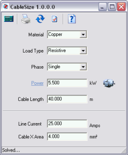
 

Using the Program

Enter the following and the program calculates line current and cable area.

  1. Conductor material.  Select from list.
  2. Load Type.  Resistive for electrical heating or inductive for motors.
  3. Phase.  Single or Three phase
  4. Power.  Use the motor button for a quick lookup.
  5. Cable Length in meter.


The normal voltage drop is based on 5.5 Volts.  You can edit this value if necessary by pressing the [Settings] button.

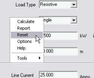
Right-Click anywhere on the form to activate the context menu.

This will allow you to activate any of the program functions and run other TechniSolve program tools that you may have installed.


Program Limits

Electrical heating loads up to 84 kW

Single phase motors up to 5.5 kW

Three phase motors up to 110 kW

How can you set the time of an S7-300 via Industrial Ethernet?

Instructions:Generally you have two options for this. You can do this either with a CP343-1 IT or a different CP (e.g.: CP343-1) and use S7 communication or UDP communication. 

  1. Here you should always use a CP343-1 IT (6GK7343-1GX20-0XE0) as communications processor, because it sets the time of the CPU via the SIMATIC procedure or via the NTP (Network Time Protocol).  
  2. If you don't have a CP343-1 IT (6GK7343-1GX20-0XE0), then proceed as described below:
    You need an S7-400 (time synchronized, e.g. via SICLOCK) which as time master provides the time to S7-300 via relevant block calls, e.g. PUT (S7 communication PUT, see point A) or AG_LSEND/AG_LRECV (UDP communication, see point B).

Configuration with SICLOCK as time master.


Fig. 01

  1. Example for setting the time in an S7-300 with S7 communication
No. Procedure
1 First configure a data block with the structure "DATE_TIME" for reading the CPU basic time in the S7-400.


Fig. 02

2 Read out the basic time of the CPU using SFC1 ("READ_CLK"). Fig. 03 shows the function call with SFC1 "READ_CLK"


Fig. 03

3 Transfer the time into a target area of the S7-300 using the S7 function call "PUT".
A sample program for S7 communication is available in Entry ID: 1819293.
4 Set the time in the S7-300 with the values transferred. Fig. 04 shows the function call SFC0 "SET_CLK".


Fig. 04

  1. Example for setting the time in an S7-300 with UDP communication
No. Procedure
1 Read out the CPU basic time in the S7-300 (as described under A).
2 Configure a connection for the UDP communication. Configuration instructions for UDP connections are available in Entry ID: 19065614.
3 In the S7-300 you program the block AG-LRECV (FC60). For S7-400 the block AG_LSEND (FC50).
A detailed sample program is available in Entry ID: 18513371.
4 Set the time in the S7-300 with the values transferred (as described under A).

Note:
The NTP procedure (network time protocol)  is also supported by the CPU's integrated interfaces and the distribution for Send/Receive can be implemented with the integrated interfaces and also with every other Industrial Ethernet CP.

How can you synchronize CPU clocks with each other?

Instructions:
If multiple CPUs are linked with each other in a subnetwork, you parameterize the clock of one CPU as the master clock. When parameterizing the CPU you also specify the synchronization interval after which all the clocks in the subnetwork are automatically synchronized with the master clock. You call system function SFC48 "SNC_RTCB" in the CPU with the master CPU. The call synchronizes all the clocks in the subnetwork regardless of the automatic synchronization. If you set a master clock with SFC0 "SET_CLK", all the other clocks in the subnetwork are automatically synchronized with that value.
 

No. Description
1 Open the Hardware Configuration in the CPU that you wish to parameterize as master CPU and open the Properties of that CPU.
2

In the Properties of the CPU you select the "Diagnostics/Clock" tab and set the type of Synchronization Mode and Time Interval as shown in Fig. 01. Then save with OK.


Fig. 01

3 Then save and compile the hardware configuration with "File > Save and Compile".

Note:
Repeat Steps 1 to 3 for all other CPU modules to be synchronized. However, for these groups you must set the type of synchronization to "As Slave".

4 Then open the dialog "Open Project" with "File > Open ..." and select the "Libraries" tab. As shown in Fig. 02 mark "Standard Library" with the cursor and then click the OK button.


Fig. 02

5 The Standard Library is now loaded into the SIMATIC Manager. Under "System Function Blocks" (Fig. 03) you will find the system functions. Copy system functions SFC0 and SFC48 by drag-and-drop to the block folder of your master CPU.


Fig. 03

6 How to set the date and time using system function SFC0 is described in the FAQ with Entry-ID 21222026.
More information on parameterizing SFC0 and SFC48 is also available in the Online Help of STEP 7 (F1 key). After loading both system functions into the CPU (master clock) all the other clocks in this subnetwork are automatically synchronized.

 Entry ID:24658964   Date:2009-03-11 

SCADA File Reference

Below is some of files for PLC, If you want download. Please Right Click on Link and Click SAVE Link As...

#