No Copy


No Right Click

Selamat Datang di Situs Belajar PLC dan SCADA

Blog gratis yang menyajikan berita seputar PLC dan SCADA.

Microsoft Windows 10

Berita seputar Microsoft Windows 10. Membahas berbagai informasi mengenai Microsoft windows terbaru.

Apple OSX

Artikel yang membahas tentang OSX terbaru dari Apple tentu sangat menarik untuk dibaca. Tak kalah serunya jika kita paham mengenai tips dan trik yang ada didalamnya.

Photography

Photography asik dan menarik jika kita mengetahuinya lebih dalam. Disini kita bisa melihat berbagai hal dari sudut pandang photo. Menarik untuk dipahami.

Thursday, April 22, 2010

Industrial Wire Management & Organized Wiring Systems

Structured cabling in commercial buildings based on TIA/EIA standards has become a common practice in many building automation system applications. Panduit is promoting similar approaches for industrial automation. Jeff Paliga of Panduit answered the following questions about their approach.
 
Why does Panduit think there is a wiring management need for industrial automation?
 
The growing number of automation devices connected via Ethernet, is significantly complicating wire management requirements across a plant or facility, forcing manufacturers to change their approach to the planning, design, and installation of a network infrastructure.
 
Without a good network management strategy in place, customers are at risk for unplanned downtime, inefficient maintenance, longer repair times, unreliable performance in harsh industrial applications, and loss of interoperability.
 
How does Panduit specifically help customers improve network efficiency?
 
Panduit Industrial Automation Solutions takes an integrated approach to the logical and physical network architecture, enabling organizations to bridge communication between factory floors and corporate offices. By integrating critical systems onto a single common infrastructure, Panduit Industrial Automation Solutions help customers improve network performance and operational efficiency, reduce operating costs, and increase productivity.
 
Panduit offers a Reference Architecture Design Guide that shows customers how to properly plan, design, and install a network. One of the main topics within the guide is the use of Zone Topology, which optimizes the amount of wiring used for a network installation. The Reference Architecture Design Guide debuted at the Automation Fair 2009 in Anaheim and is available free by registering at www.panduit.com/IA
 
Panduit’s Reference Architecture Design Guide
 
How does Panduit specifically help reduce operational costs?
 
Panduit solutions provide quick and dependable installations for greater reliability, availability, and security - and help improve mean time to repair (MTTR). Our solutions deliver measurable efficiency gains in the areas of space and power consumption across critical systems, contributing to sustainability and operational efficiency.
 
How does Panduit address physical security?
 
To help keep a network secure, Panduit takes a multi-layered approach to network physical security. For example, Panduit has “Lock-In, Block-Out, and Keyed” systems that are simple to install and deter unauthorized access of the physical layer.
 
There seems to be a pattern to the colors of connectors, cables and other wiring management?
 
Color-coding is a simple technique that is used within networks helping identify redundancy, VLAN, location and functionality. Panduit offers several products such as different colored communication cable, color-coded jacks and patch cord bands, and Tak-TyÃ’ Hook & Loop tape for ease of cable bundling and identification to help take the guess work out of troubleshooting, moving cables, adding cables and making changes. This also results in lower MTTR.
 
 
Color Coding & Physical Network Security
 
You also integrate fiber optic cables, how is it being accepted?
 
In network designs, the use of optical fiber continues to grow due to performance, noise immunity and distance criteria. Fiber has been saddled with a perception that it is difficult to field-terminate [i.e. polishing and testing]. The Panduit OptiCam™ fiber system and tooling delivers superior performance parameters, eliminates the need for field polishing, and offers visual indication of proper termination to virtually eliminate operator error.
 
 
OptiCam™ Fiber Termination Tool
 
What specific problems does Panduit's wiring management solve?
 
The Unified Physical Infrastructure℠ approach, or UPI, helps customers simplify networking, speed deployment, ensure harsh environment performance, and save valuable real estate on the manufacturing floor and critical infrastructure like control panels. For example, Panduit PanelMax™ DIN Rail Wiring Duct increases panel layout space and installs 40% faster than traditional methods. Another way we help our customers reduce risk is with a patching technique that allows easier terminations and pre-testing for verification of critical links. The resulting benefits are lower installed cost by reducing the number of rejected connectors and terminations since the Panduit optical fiber solution allows up to two re-terminations that provide yield rates approaching 100%.
 
What types of system network cabling does UPI address?
 
The UPI approach enables organizations to converge communication, computing, control, power, and security systems resulting in a number of benefits including lower life cycle cost, higher reliability and lower time to repair.
 
 
Panduit UPI-based solutions for Industrial Automation offer a system that manages, connects and protects wire for electrical, control and networking applications. These solutions enable distributed control systems to be used across all manufacturing areas, providing a structured method of deploying physical infrastructure elements that will withstand harsh factory floor conditions while optimizing network performance and safety. Five targeted Industrial Solution Groups address a user’s needs from panel to plant:
 
  • IN-Panel: Control Panels, Electrical Panels, Specialty Panels and MCC (Motor Control Center)
  • IN-Room: Micro Data Center (Control Room area)
  • IN-Route: Network Distribution Pathways
  • IN-Field: Machine-mounted systems
  • IN-Frastructure: Industrial lighting, HVAC, security systems
 
Can you provide some specific examples of new hardware to organize wiring beyond standard wire duct?
 
Some new exciting products include the J-Pro™ Cable Support Systems which support open style routing of network cables. Inside a control panel, there are Fiber Slack Manager devices that maintain bend radius for fiber optic cables. And Dynamic Cable Tie Managers that provide strain relief for cables in area of movement (ie. on a control panel door).
 
 
J-Pro Cable Support System
 
 
Dynamic Cable Tie Manager
 
What kind of results are users having with this approach?
 
Customers have validated each level of our architecture concerning the value of the solution approach that addresses performance, security and maintainability. We have seen end users design control panels with 30% panel space savings, while ensuring performance with our noise mitigation solutions. Our fiber and copper solutions are being installed in zone architectures, leveraging Stratix™ Switches from Rockwell Automation to provide high performance, maintainable systems that minimize downtime. Our high quality termination solutions have helped customers with reliable connections throughout the physical infrastructure, and meeting standards including UL, CSA, IEEE Std 837-2002, and American Bureau of Shipping.
 
What are plans for the future?
 
Panduit is uniquely qualified to understand the complexities of plant-level networks, from monitoring production processes to optimizing pathway design. Panduit will continue to deliver UPI (Unified Physical Infrastructure) solutions for the manufacturing physical layer to efficiently manage converged networks for industrial applications.
 
Panduit New World Headquarters – opening April 2010
 
Our customers and our channel are looking for faster ways to deploy the network infrastructure. We are constantly working to deliver unique and optimized systems that provide measurable value to our customers and partners.
 
Our new World Headquarters building, located in Tinley Park, IL, is a “living lab” demonstrating the UPI vision, in which critical power, communication, computing, security and control systems align contributing to our sustainability goals through a lower carbon footprint and energy savings of up to 20%. Through continued application research and collaboration with fellow industry leaders, we will enable customers to achieve greater ROI and meet their sustainability goals.
 
More Information: www.panduit.com; email: cs@panduit.com

Satellite systems control Spanish wind farms

Iberdrola Renovables says it is a world leader in electricity production from renewable sources. From its operations centre at Toledo, 70 km south of Madrid, it controls ten wind farms that total 9,600 MW. The communications link is provided by a private satellite network.


Previously each wind farm was monitored from one local SCADA station by telephone. All the required data were saved to disk which was then passed to whoever did the data recording.
To modernise the operation, the company chose Paris-based ARC Informatique´s OPC-based client-server SCADA software, PcVue, and several FrontVue light clients.
The main objective of the project was to gather information from the wind farms, especially alarms and historical data. The control system at each site samples the main operational data from the generators and the various substations. The operations centre uses these data to identify and diagnose potential problems and so to intervene to effect a solution.
Windows-based PcVue and FrontVue are capable of managing millions of I/O points online from thousand of devices. Up to 2.5 million data items are monitored by the FrontVue client stations, which communicate via OPC with the front end over a 1,000 Mbps redundant TCP/IP Ethernet network. Each front end can receive up to 60,000 I/O points. Currently they are 13 PcVue file servers that manage a million real-time variables and the network can be extended without limits or structural changes.
Using the PcVue-FrontVue architecture, the operators can analyse the data from the remote wind farms in detail. They always have the situation under control and can perform corrective actions at the right moment in case of breakdowns.
Given the huge volume of data (around 350 points per turbine) and so as to ease maintenance operations, the supervision takes place at two levels:
* The upper level gives a panoramic view of the most significant alarms, data values and counters, as required for monitoring the turbines and to detect faults that require intervention;
* The next level is more detailed to enable better analysis of all the data from the turbines so that the operators can immediately and accurately diagnose problems and take appropriate action.
All of the data received are processed by way of setpoints, historical data, alarms and trends.

Contact Detail/Archieve:

ARC Informatique

2 Avenue de la Cristallerie
92310 Sévres
France

Telephone : +33 4 76 182 912
Fax : +33 1 46 23 86 02
Web : www.arcinfo.com

Invensys launches new SCADA and EMI software

Invensys Operations Management has launched its InFusion SCADA 2.0 software system, with Foxboro® SCD2100 and SCD2200 remote terminal units for oil and gas and water and wastewater applications. The company has also introduced its Wonderware® Intelligence Software 1.0 solution, which it calls an “enterprise manufacturing intelligence (EMI) solution.”

The SCD2200 RTU is a larger modular station for more complex 
applications, which may require central stations and redundancy.
The SCD2200 RTU is a larger modular station for more complex applications, which may require central stations and redundancy.
SCADA systems technology is used to optimise real-time monitoring, data acquisition, communications and control for geographically distributed industrial operations, especially those in which data collection and transmission might be subject to unintended interruptions.
Chris Smith, SCADA product manager, says the new offer draws on the company’s 40 plus years of SCADA heritage and includes some of the industry’s most advanced integration, interface and control technology capabilities.
“Robust, reliable monitoring of remote operations can mean tremendous savings in reduced downtime, efficient maintenance and improved security. And cost-efficient configuration, integration and scalability translate into further savings,” said Mr. Smith, SCADA product manager.
“The new SCADA system software and RTUs deliver unprecedented network SCADA monitoring and supervisory performance and maintainability for industry, along with simplified interaction and management for today’s rapid-growth SCADA implementations.”
The package of software components enable SCADA developers to create reusable objects and templates, as well as manage HMI display properties, data quality, equipment maintenance tagging and other functions necessary for building SCADA applications.
The system also stores program components in a central repository for remote deployment to Windows-based network devices. End user engineers can then draw on this repository to build future applications, which enforces standards, preserves applications knowledge and reduces the overall engineering effort.
System managers can also propagate changes to multiple computers with a single mouse click, reducing travel and SCADA network troubleshooting costs.
As a backup to customer’s engineering teams, an InFusion SCADA Device Relationship Management software agent provides secure Invensys-based remote backup for any installed system, giving the owner more confidence that any alterations or performance issues can be monitored and diagnosed by authorised Invensys expertise.
The new SCD2100 and SCD2200 remote terminal units (RTUs) provide an integrated operating environment for controlling and monitoring field operations and collecting real-time data for viewing via InFusion 2.0 screens or integration with process control or other enterprise applications.
Both of the new RTUs support a wide range of input/output configurations and device integration, including support for the HART protocol.
They also support pre-programming of ISaGRAF IEC-61131 and IEC 61499 compliant function blocks, which delivers faster processing and sequencing than conventional RTUs that interpret programming languages at run time. This provides for more field automation applications for improved unattended operations.
Both RTUs also include function blocks certified for oil and gas industry calculations and are available with TCP/IP or wireless connectivity.
The SCD2200 RTU is a larger modular station for more complex applications, which may require central stations and redundancy, such as upstream oil and gas well monitoring, wet gas, oil and gas transportation facilities and pipelines and high-level well control.
It is also suitable for large utility applications.
The SCD2100 RTU is the more compact of the two RTUs and is especially suitable for very low-power operation on oil and gas, as well as water and wastewater. The low power SCD2100 unit is certified for explosive environments
The compact SCD2100 RTU is suitable for very low-power operation, 
and is certified for explosive environments
The compact SCD2100 RTU is suitable for very low-power operation, and is certified for explosive environments
The new SCADA offerings provide an industry-specific system solution with industry applications, such as the Wonderware Water and Wastewater Industry Pack, as well as with other Invensys automation products, including SimSci-Esscor simulation software, Foxboro distributed control systems, Triconex critical safety systems and Avantis enterprise asset management software.

Wonderware Intelligence 1.0
Invensys Operations Management also introduced its Wonderware® Intelligence Software 1.0 solution, which it calls an “enterprise manufacturing intelligence (EMI) solution.”
The software enables customers to contextualise, aggregate and report both historian and operational data using role-based dashboards, presenting key performance indicators (KPIs) and real-time operational business metrics that are used to monitor, tune and optimise operations and supply chains.
The purpose of the software is to transform data and information from multiple sources into business intelligence by aggregating process and production data in real time and adding contextual elements, such as equipment, product, work orders, material and personnel.
The information context is aimed at enabling end users to gain insights into the root causes of problems and understand how production events are related.
The formatted information is saved and optimised for fast reporting and analysis, allowing end users to create and publish dashboards using the Wonderware Intelligence Analytics Client into a variety of web portals. Users can also configure customised metrics without programming.
IOM says other features of the software include:
* Acquires data not only from the Wonderware family of products, including MES, InBatch™ and Historian, but also from external systems such as ERP, LIMS, PDM or even other execution systems and historians, to provide plant, multi-plant and corporate-wide views of operations and performance.
* Utilises tools to rapidly create and publish dashboards that can be rendered in commonly used web platforms such as Microsoft SharePoint®, mySAP Enterprise Portal and Wonderware Information Server.
* Furthers investments in the core Wonderware products, leveraging System Platform’s Integrated Development Environment and services for configuration and deployment of the data model and allowing customers to incrementally add MES and EMI features and functionality easily and non-invasively.
* Is a cross-functional product, applicable to any industry or market segment
“This is a true EMI solution that allows customers to build once, deploy at multiple sites and enjoy corporate-wide visibility of their plant’s KPIs, even with disparate data sources,” said Maryanne Steidinger, director of product marketing, Invensys Operations Management.
“Dashboards can easily be created with drag-and-drop ease, enabling self-service access to information.”

Tuesday, April 13, 2010

Free software developed to help with ATEX and DSEAR design and verification

A range of free software has been developed by ExVeritas to assist people involved in the design or verification of ATEX and IEC products or sites with explosive atmospheres. The software runs ‘on line’ or can be downloaded as a desktop application under Windows.

Free software to help with ATEX and DSEAR design and verificationThe software will also run as an iPhone/iTouch Web Application. Currently the software includes:

FlamCal
ATEX and IEC Flammable Properties Application: This application allows the user to select from several hundred common flammable substances to determine the physical properties that may be required for ATEX or IEC equipment selection or area classification. You would need 30+ A2 ATEX Posters to hold this much information!

IntrinsiCal
ATEX and IEC Intrinsic Safety Circuit Evaluation Application: This application gives an indication of the maximum safe voltage, current, capacitance and inductance to use when designing a circuit to be energy limited or Intrinsically Safe

MESGCal
ATEX and IEC Flameproof Design Application: This application is designed to provide a designer or an inspector with an indication of the correct maximum safe gap for any selected Flamepath type.

Further applications will follow, including tools for area classification, SIL and risk assessment. The software can be run on line or downloaded from www.exveritas.com

Prosoft: High Speed Wireless Communication Module for Rockwell

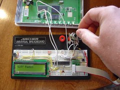
Wifi Radio Tuner Control DemoImage by mightyohm via Flickr
age via Wikipedia

MVI56-WA-PWP

The MVI56-WA-PWP Wireless Gateway creates a powerful wireless connection between devices located remotely, and the MVI56-WA-PWP in a ControlLogix rack.

Features and Benefits

ProSoft Wireless Protocol (PWP) offers versatility where a mix of control devices requires cooperation with each other. This involves sharing of information across the applications regardless of device or network type, often at high speed. Wireless bandwidth utilization is optimized by using efficient communication methods. The protocol supports Unicast, Broadcast and Multicast group messaging. Efficiency is based on the fact each device on the "wireless" network can produce these types of messages and each device determines which of these messages to consume.

Applications

The module offers one-to-one or one-to-many wireless connection scenarios. Data is exchanged between devices and/or networks using an efficient but powerful wireless protocol. This common database provides the backbone communications for various field devices using different networks.

Functional Specifications


General Radio Specifications

  • Frequency: 2.4 GHZ band (2400 to 2483.5 MHz)*
  • Wireless medium: DSSS - Direct Sequence Spread Spectrum
  • Output power: 32 mW (15 dBm), Up to 500 mW (27dBm) **
  • Channel data rates: 11, 5.5, 2, 1 Mbps
  • Channels - user selectable:
    • 11 - North America
    • 13 - Europe***
    • 14 - Japan
  • Outdoor Range: up to 20+ miles **
  • Security PWP + WEP 64/128 Encryption
  • Antenna Ports (2) RP-SMA connectors, automatic antenna diversity
* Varies with country regulation
** With external amplifier, varies with country regulation
*** Some European countries such as France allow fewer channels

Hardware Specifications


Specification Description
Backplane Current Load 800 mA @ 5 V
Operating Temperature 0 to 60° C (32 to 140° F)
Storage Temperature -40 to 85° C (-40 to 185° F)
Shock: 30g Operational
50g non-operational
Vibration: 5 g from 10 to 150 Hz
Relative Humidity 5 to 95% (non-condensing)
LED Indicators: Module Status
Backplane Transfer Status
Application Status
Serial Activity

Wireless Specifications

Specification Value
Frequency 2.4 GHz band (2400 to 2483.5 MHz)*
Wireless medium DSSS - Direct Sequence Spread Spectrum (802.11 d)
Output power 32 mW (15 dBm)
Channel data rates 11, 5.5, 2, 1 Mbps
Channels - user selectable 11 - North America
13 - Europe**
14 - Japan
Security PWP + WEP 64/128 Encryption with WEP key rollover management
Antenna Ports (2) RP-SMA connectors, automatic antenna diversity
Bit Error Rate (BER) Better than 10^5
Range / Transmit Rate High Speed
11 Mb/s
Medium Speed
5.5 Mb/s
Standard Speed
2 Mb/s
Low Speed
1 Mb/s
Open Office Environment 160m
(525 ft.)
270 m
(885 ft.)
400 m
(1300 ft.)
550 m
(1750 ft)
Semi-Open Office Environment 50 m
(165 ft.)
70 m
(230 ft.)
90 m
(300 ft.)
115 m
(375 ft.)
Closed Office 25 m
(80 ft.)
35 m
(115 ft.)
40 m
(130 ft.)
50 m
(165 ft)
Receiver Sensitivity 83 dBm 87 dBm 91 dBm 94 dBm
General range guidelines (actual results may vary)
* Varies with country regulation
** Some European countries such as France allow fewer channels

Related Information
Image Gallery


Ordering Information

MVI56-WA-PWP High Speed Wireless Communication Module
Reblog this post [with Zemanta]

New DCS for the Power Industry, the Siemens SPPA-T3000

Transmission linesImage via Wikipedia
By Bill Lydon - Editor
 
I recently visited Siemens Energy’s Instrumentation, Controls, and Electrical group to learn more about the SPPA-T3000 system and how customers are using it. 
 
Mike Korf, Director of Sales & Marketing for Siemens I&C, set stage with a discussion about Siemens involvement in the power industry. Korf elaborated on the products they offer for planning, construction, service, optimization, modernization, and life time extension for power systems.  The group’s product offerings include SPPA-T3000 Control System, SPPA-D3000 Diagnostic Suite, SPPA-E3000 IEC 61850 Electrical Solutions, SPPA-P3000 Process Optimization Software, SPPA-M3000 Energy Management Software, SPPA-R3000 Turbine Controls, and SPPA-S3000 Simulator.
 
Korf clearly defined this group’s role, “if it makes megawatts, this organization takes care of it.” Korf noted the wide range of applications including: waste incineration plants, wind power plants, nuclear power plants, industrial power plants, biomass power plants, fossil fired plants, combined cycle plants, desalination plants, coal gasification plants, and district heat plants. In North America, Siemens systems are used in more than 250 power plants. Siemens’ new SPPA-T3000 system is being deployed in over 80 power plants in the U.S. and Canada.
 
Migration
Steve Leibbrandt, Siemens CTO, discussed the pressure on existing power plants to meet more demanding market requirements and deal with aging control systems. Power plants need better control to respond to constantly changing operating parameters, such as fuel costs, multiple fuel tradeoffs, and widely varying power demand. Maintaining older systems becomes more costly and challenging with the obsolescence of key components, inability to increase efficiency with new technology, and price increases on replacement parts.
 
Total system replacements pose a number of expensive problems; including long plant outage time, significant project re-engineering, commissioning, normalizing plant operations, and new as-built drawings.
 
The alternative is a phased modernization to minimize risk and maximize investment return. The migration focuses on replacing the front end computers, software, and field controllers. The majority of I/O modules, field wiring and sensors are kept in place. This approach enables you to leverage the latest asset management and optimization software to gain greater efficiencies.
 
Siemens SPPA-T3000 System
I was surprised to learn that the Siemens SPPA-T3000 system software was completely designed in the United States, including the engineering design tools.
 
Leibbrandt illustrated Siemens’ analysis of the DCS architecture evolution from isolated sub-systems, interlinked sub-systems to fully embedded functionality, which Siemens believes the SPPA-T3000 has achieved. Leibbrandt believes that 95% of existing systems are based on the older less efficient architectures.

 
The SPPA-T3000 system is a modern, Java-based design with system software running on a redundant Stratus server. Networking between the controller and application server is PROFINET and supports redundancy. The SIMATIC S-7 controllers, referred to as Automation Servers, network to the field using Profibus DP.
 
 
Field controllers are Siemens SIMATIC S-7 controllers, but they are programmed with the new IDE specifically designed for the SPPA-T3000 system.
 
Integrated Design Environment (IDE)
The system has a single integrated design environment for creating HMI screens and logic, allowing for efficient applications development. The entire system software goal is to have one integrated engineering software tool. At first look, the design tools are integrated and straightforward to use. It would take a more in-depth analysis to really understand the use and limitations of the software.
 
This was all developed in JAVA and all operator stations, HMI, and engineering stations are thin client WEB browsers. The only place system software resides is in the redundant server, simplifying software maintenance. Siemens offers software to automatically import configurations from older systems for migration projects.
 

Logical Engineering Function Block Programming
 
Logical Engineering Changed to SAMA Drawing
 
Software Architecture
David Clout, Product Manager, explained that the system software architecture is based on a Java framework from ilog (www.ilog.com ), an IBM company. Algorithms for function blocks are written in JAVA and stored as an XML file. The software has a parser and other code that tokenizes the logic in a form understood by the controller runtime software engine in an S-7 controller.
 
 
The system programs like a DCS with using industry symbols, faceplates, and other common industry elements.  The new software, with an IDE, has made the system much easier to use and understand. Clout described how the basic training program for the software has been reduced from a 5-7 week training program to 4 days.
 
OPC is used as the primary interface to other software such as process management, enterprise, and asset management.
 
Customer Experience
Steve DiCarlo, General Manager at the Carneys Point New Jersey Generating Plant, owned by Cogentrix, discussed his plant control system upgrade last spring with the Siemens SPPA-T3000 system. The plant is a 266-megawatt, pulverized-coal cogeneration facility that supplies steam & electricity to the DuPont Chambers Works next door. On average the plant delivers about 250 pound per hour steam and about 20 megawatts of electricity. The plant is designed to generate one million pounds per hour of steam and 40 megawatts to DuPont. They are able to sell excess energy to the grid. The plant has 30-year deals with DuPont and Atlantic Electric, the local utility. Some of the excess power is sold at fixed price and the balance sold on the open market. 
 
A big driver for them was obsolescence - their Westinghouse Distributed Processing Family (WDPF) DCS was not going to be supported. Parts, service and support was becoming more difficult. Also, they wanted to coordinate the change with the major overhaul they do about every 7 years when the turbine and boiler are down. There have only been two shutdowns coordinated with DuPont in 15 years. DuPont agreed to give them 60 hours for a shutdown without steam.
 
DiCarlo selected Siemens based on his previous experience in 2004 with a Siemens replacement of proprietary controls on an Alstom machine. The old proprietary control system required expensive specialists from Europe to troubleshoot and make changes. DiCarlo learned from this plant system experience, saying, “We have to get something here that we can understand and have support here in the states.” He further noted, “Going non-OEM controls in our industry is always tough - there are a lot of people that will certainly criticize you if it didn’t work out.”
 
They had a very successful WDPF migration and were back online in 55 hours. Operations were restored with full steam capacity to DuPont Chambers Works without penalty. This was accomplished with detailed planning, and pre-outage mockup installation with Carneys, subcontractor, and Siemens’ project team.
 
 
Cabinets made of wood were used as mockups to train installers.
 
The Ad-Con 4W is a special connector developed by Siemens, the Ad-Con 4W that is used to make a direct connection between new input/output modules and the existing field wiring. The existing WDPF DPU’s and Q-Crates are removed from the front of the cabinet, while the field termination half shells are untouched at the rear side of the cabinet. The Ad-Con 4W connector interfaces the existing WDPF card edge connectors from the half shells and mates them to the new Siemens S7 input and output modules.
 
 
During the changeover there were teams of people at each cabinet.
 
DiCarlo noted that they can make changes quickly and efficiently because the software is easy to use and changes are made without system interruption. Also, troubleshooting is easier since they can look at the logic in real-time to see what is happening.
 
Jim Sousa, General Manager at the Logan coal fired power plant at Swedesboro, New Jersey, another Cogentrix operation that is in the process of upgrading to the SPPA-T3000, commented on their system. Logan is a 245-megawatt, pulverized-coal fired plant. The SPPA-T3000 control system is to replace controls for one Westinghouse steam turbine, one 100% Foster Wheeler boiler, and balance of plant controllers. The system has a number of interfaces to the existing I/O including 3,500 WDPF IO, 11 serial links, Allen-Bradley DH+, Forney BMS (Modbus), and 3,000 Serial I/O.
 
Conclusions and Observations
 
Software IDE
After a brief look at the software, it appears to be a clean design that is easy to use. The integration of the control logic and HMI development tools into a single application allows for interactive development of the initial project and ongoing refinement and improvements over time.
 
Thin Client Browsers
A central application server has the advantage of simplifying software maintenance with only one location for software revision updates. The server and communications become critical to total systems availability in this configuration and this has been addressed with the Stratus non-stop computing configuration and redundant communications networks.
 
Function Block Programming
The system relies on function block programming and the user can create additional blocks using the existing function blocks. Engineers can switch between IEC and SAMA logic symbols views. The software has the facility for task scheduling and prioritization similarity to the IEC 61131-3 standard.
 
Controllers
The Siemens SIMATIC S-7 controllers referred to as Application Servers in this architecture are refined and established hardware platforms with a large set of I/O interfaces. 
 
System Interfaces
The SPPA-T3000 system has interfaces for a wide range of other systems including Modbus (Serial & TCP/IP), IEC60870-5-101 (serial), IEC60870-5-104 (TCP/IP), DNP 3.0, IEC 61850, Allen Bradley Data Highway Plus (DH+), Allen Bradley EtherNET/IP, GE GSM, TELEPERM ME, SIMATIC S7 400 IA, and SIMATIC S7 300 IA.
 
Bottom Line
This Siemens group is dedicated to power applications and has designed the SPPA-T3000 specifically for the power industry.
 
If you are in the power industry and looking at upgrading control, I suggest you should develop your operational goals for an upgrade, define criteria to measure solutions, and add the SPPA-T3000 to your list of possible choices.  More Information.
 
Sumber: www.automation.com
Reblog this post [with Zemanta]

Monday, April 12, 2010

Advanced HMI - The Free HMI / SCADA Development Package

Use freely available software to develop an HMI that works with Allen Bradley SLC500 and MicroLogix. Don't miss the Advanced HMI project that extends this driver by adding some very nice graphical controls. It can be found at:


http://sourceforge.net/projects/advancedhmi/  or http://advancedhmi.sourceforge.net/


Using Visual Basic 2008 and these controls, you can easily build a superior eye catching HMI. Includes DF1 serial and Ethernet/IP driver for Allen Bradley SLC and Micrologix PLC. You can directly access the driver to perform about any task in code. Free Download.


PLC Videos Basic

Buat mahasiswa atau kita" yang ingin mengetahui aplikasi PLC, silahkan lihat di video di bawah ini.


New control platform with motion control for wafer handling

Software standards make the change of hardware platforms easier

Nowadays the choice of a suitable hardware platform for a machine control is not an ever lasting decision and change over time can be needed. There may be many different reasons for such a change in controller platform. Sometimes, economical considerations are decisive for instance to move from a PC-based controller platform to an embedded version: after a number of machines of the same series the machine becomes more a commodity and a customized embedded controller can be a more economical hardware solution for the future. Even though the first series have been realized with standard controllers, the long-term competitiveness requires a change of the hardware over time. Often there are functional and technical aspects that are decisive for a change of controller hardware: previous controller variants quickly reach their functional limits due to a change of the high level machine design or a different strategy of the machine modularization, new networking requirements or operational requirements of older controller products. Only the porting to a new platform prepares the ground for the desired machine design.  
This probable change make it for the machine manufacturer very impor­tant to have an software application which is hardware independent and which flexibility supports the hardware change. For the control supplier it should be part of the customer orientation to supply its products with standar­dized programming tools.

New control concepts – fit for change

As a partner of mechanical engineering who recognizes and implements trends at an early stage, ECKELMANN AG operates  in all controller solutions (CNC, PLC, motion control) with different hardware platforms that have been developed and manufactured by ECKELMANN AG: PC-based, standard embedded controllers as well as completely customized hardware. Own software libraries are available for the three field of application CNC, PLC and motion control which can be used in an identical way on all mentioned hardware systems.  
The typical controller functions of the three software libraries CNC, PLC and motion control can be called by the user in the form of function blocks which are part of the IEC 61131-3 programming tool CoDeSys. The support of such a software standard offers a variety of advantages to program­mers and end users who mainly benefit from the broad testing and quick further development of these pro­gram­ming stan­dards. Within the meaning of the above-mentioned strategy of a platform-indepen­dent controller concept, the use of a standard such as CoDeSys, moreover, creates the ideal pre-requisites for all types of program porting or for system change with simultaneous maintaining of the application software. Software standards offer safety and protect valuable investments made for the preparation of applications.

Application example: Tec-Sem switches over to embedded controllers for the wafer stocker Pr@ctor

Tec-Sem, Tägerwilen , Switzerland is established both as leading manufac­turer of systems for the semiconductor industry and as supplier of OEM auto­ma­tion solutions for semiconductor tools. In particular, Tec-Sem is marketing pro­ducts for wafer management without using cassettes. In 2005, the product series Pr@ctor was put on the market as a new, particularly flexible system. Pr@ctor is a system which combines the functions of stocking and sorting of 300 mm wafers in one tool – in addition measuring systems can be integrated.  
The wafers are delivered via two to four load ports. The wafer ID is read in the handling and verification unit by means of a high-speed standard robot and a special aligner and the stocking in the connected storage towers is pre­pared via a buffer. The quick stocking without cassettes is designed mainly for highly complex applications with mixed, small production lots, increase require­ments on cleanrooms and a high number of different wafer qualities.

Fig. 1: Tec-Sem wafer stocker Pr@ctor
 
Besides the robot and the aligner of the handling unit, in particular the handling axes and the lifting drives of the cassette-free storage towers are to be controlled in this machine. While the first models of the Pr@ctor series were equipped with PC controllers, very soon embedded controller solutions have been searched for reasons of modularization. The choice fell on the ExC55 con­troller of ECKELMANN AG. Equipped with the software module library „Motion“, this embedded controller forms the complete controller EMC55 for motion control applications of 2 up to 64 axes.

Fig. 2: Latest embedded controller of ECKELMANN AG

The motion control function blocks of the EMC55 are in compliance with PLCopen and the programming standard IEC 61131-3. Based on this Tec-Sem is able to port the available controller software at a ratio of 1:1 to the new hardware platform. An additional advantage as far as compatibility is concerned is the controlling of the drives via the standard CANopen interface as per DS402 (interpolated position mode).
In fact, this change of system can be realized so smoothly that the change-over could be carried out at the sole responsibility of the machine manufac­turer. Additional programming expenditures or parameterizing did not incur. Sometimes it is very easy to find a new home for a proven machine controller.
Fig.3 : Splash screen of the Pr@ctor user interface

Tevopharm introduces Packaging Machine with PLCopen Motion Control inside.

Tevopharm BV, The Netherlands, developed a new packaging machine, which is completely based on IEC 61131-3 and the PLCopen Motion Control Specification for logic and motion control. This certainly can be seen as a proof of concept. This article describes the origin, the implementation, and the benefits.


1.1. Introduction into Tevopharm Tevopharm

B.V. was founded in 1959 in Schiedam, The Netherlands. With a crucial patent in flow-wrapping, it quickly became a large manufacturer of high quality horizontal bag form, fill and seal machines for packaging of chocolate and bar products, biscuits, candies and pharmaceutical products. Their PACK-6 flow wrapper was seen by the market a as a de-facto standard.

In 1985 it became Klöckner Tevopharm, and in 2003 it was taken over by Bosch.

The Dutch company has about 175 employees generating annual sales of approximately 30 million Euros. With over 5,000 flow wrapper machines sold, it is worldwide active, with approximate turnover of 35% in Europe, 35% in North America, and 30% in Asia and the rest of the world. Their product range from stand alone applications with single servo systems till full servo controlled, turn-key multiflow wrappers, including distribution, storage and multilane flow wrapping, grouping, and secondary packaging systems, to serve the world’s largest food manufacturers.

Due to the changes in consumer behaviour, requiring smaller portions of food and a wider variety, and the stricter hygiene demands, an increased interest in flexible automated packaging productions lines operations will boost future demand.

1.2. Introduction of the machine

The first machine fromTevopharm that is build around the PLCopen Motion Control Function Block Library is the PACK-300CA Flow Wrapper. This machine is capable of packing up to 2,000 products per minute.

Where the PACK-300CA is the first Tevopharm machine to be equipped with the new control system, the other full servo-based machines PACK-200 and PACK-2000 will follow shortly.


Picture 1: The Tevopharm P300 CA packaging machine


Picture 2: The scheme of the P 300 CA machine

The PACK-300CA contains three servo drives steering the following functionality:

  1. The product infeed chain (M1)
  2. The film feeding and alignment (M2)
  3. The cross sealing part (M3)
To control these servomotors a 'virtual line shaft' is used in the controller. This virtual line shaft operates the machine just like a traditional mechanical line shaft, while adding the flexibility which the mechanical version is lacking. All servomotors are coupled to this virtual line shaft via the control software.

The infeed servo has a one-to-one relationship to the virtual line shaft, and can therefore be seen as the physical representation of the virtual line shaft. The second motor follows the virtual line shaft, while keeping the print on the film aligned with the rest of the process. The third motor is coupled to the virtual line shaft via a specially designed profile. This profile assures that the sealing and cutting of the film is done at the right place and with the right speed.

Controller & architecture

Basically all packaging machines have three basic control functions:

  1. HMI, the Human MachineInterface
  2. PLC, the logic part of the control
  3. MC, the Motion Control functionality
Normally each function can have different suppliers, especially on request from the end users, making a wide mix possible. With the PACK-300CA, these functions are merged. Integration into one platform, like PC based control, can be possible. However certain software constraints, as well as ability to serve different customer expectations on the HMI part, makes a preference for the integration of PLC and MC into one platform, and the HMI on another one.

1.3. Rationale of using IEC 61131-3 and the PLCopen MC

Due to their worldwide operation, Tevopharm has to support multiple platforms as requested by their customers. Support for multiple platforms results in a high cost content in the software, due to multiple training costs, multiple application developments, multiple debug sessions, and increased installation and maintenance costs. Since the resulting machine basically does the same job, these quality-related costs induce a large effect on the price of the machine, the delivery time, and the time to full production.

To reduce these costs and to create optimum customer value, a hardware-independent development of the application software is needed. With this, the relevant software can be used on different hardware platforms without much additional costs. This provides the users customers a wider choice of electrical hardware, optimised to their high value, slow moving electrical-parts-stock.

To provide this, a high level of standardization is needed, especially in the software section.

Around five years ago, Tevopharm initiated a project for the PLC software development to move to configurable elements as provided by the worldwide programming standard IEC 61131-3. This means that the functionality of the each application program for the machine was constructed from a pre-defined and tested set of building blocks. With the implementation done, they saw a large improvement in the quality of the software, and a large reduction of the associated costs. This cost reduction was not only valid at Tevopharm, but also at her customers.

The next logical step in this was to include the motion control section. At that time, their motion control consisted of two different environments, using two different languages, in this case “C” and “structured text”.

Around 2001, Tevopharm became aware of the PLCopen initiative to harmonize the access for motion control via the IEC 61131-3 programming environment. PLCopen had just released the first part of this specification, and several suppliers were in the process of converting this to real products. With this motion integration, Tevopharm would be able to use the same environment with the same language for both the logic control and the motion control. However, they wanted to make sure that the specification overall would suit their needs. To support this, they joined PLCopen and helped working on the next parts of this motion control specification.

Using the short list for compliance, as provided by PLCopen, Tevopharm could very easily specify their own requirements for their motion control environments, merge this with their additional requirements, and select potential suppliers based on this.

For the PACK-300CA machine, Tevopharm basically used a selection of the function blocks of part one, and a sub set of part 2.

1.4.Standardization and the software development process

The structured approach (see sidebar) created the basis for configurable software. This means that for the whole set of machines as provided by Tevopharm, there is basically one program developed per control hardware platform. With further standardization this can even go one step further: one software program for different (read: all) platforms.


Picture 3 - Application software development as basis for multi-level machines

In addition, the application software functions parts need only to be debugged once, while being used on multiple platforms. Higher reuse of software results in less cost and less delivery time to full production at customer’s site. This includes the higher functionality of the PLCopen MC FBS as provided.

With this approach, Tevopharm enhanced their quality of their application software, as well as the development of this. This helps them to fulfil the requirements needed to achieve CMM level 2. (CMM = Capability Maturity Model.)

1.5. Resulting benefits in training, service, support, and maintenance

This approach results in a reduction of the training costs ? both at the supplier and the user. Besides the reduction in training needed, the needed level of education is reduced. Moreover, this makes the service people more flexible.

With the commonality at a higher functional level, coupled to a better error tracing method and added debug functionality routines also to a deeper level in the HMI, the machines are simpler to operate and maintain, resulting in less need for assistance. This supports the philosophy of life cycle cost reduction. The end user easily sees these reduced service and maintenance costs, resulting in a high level of acceptance.

Overall, the usage of world wide standards offer for both the OEM suppliers as well as the users, clear benefits:
  1. A world wide software standard which everybody can easily learn and understand;
  2. The development and installation of new machines is faster, more predictable, and easier. This results in shorter installation time of the machines with less risks, meaning a quicker productive line: what used to be up to one month to check the last bugs during full size production can now be done in days, benefiting from the improved software quality;
  3. The software for a particular machine is no longer developed for a particular hardware type or brand. If a hardware platform becomes obsolete, or the supplier even ceases to exist, the investment in the software is largely protected as it can easily be ported onto a different hardware brand. This secures the customer investment.

Application software development more independent of the hardware

Via standardization and modularisation, Tevopharm protects their investments in software. If one of their customers needs a new functionality, the resulting software can easily be added to the standard in-house software library, if desirable.

This also means that the initial added software investment could be carried by future deliveries also, increasing the efficiency and protecting the investment, while being open to the future. And it provides their customer with more choices in platforms at lower costs and risks.

Standards used at Tevopharm:

The software application development is just one part of a complete operating machine. Other environments have to be considered. Tevopharm uses additional standards for this. These include IEC 61131-3, PLCopen Motion Control, PackProfile and PackML State Model as defined by the OMAC Packaging Working Group (see insert), Sercos as drive interface, and DeviceNet and Profibus as I/O interface.

Current investigations also include a one-CPU architecture for HMI, PLC, and Motion. This should add to the transparency of the overall system, and give access to the latest develop­ments in the Intel architecture, now and in the future.

1.6. What was learned?

A user (customer) already familiar with the IEC61131-programming standard and the PLCopen Motion Control functionality easily can read a program. The same ‘look and feel’ principle to be achieved works in reality! When machine vendors make use of hardware specific extensions to the specified functionality, the similarity is starting to vanish, leaving customers with the need of hardware specific training for their maintenance people.

The above statement is the confirmation that it is indeed preferred to use the basic PLCopen Motion Control Function Blocks, and to neglect hardware supplier specific options.

During the work, Tevopharm experienced a contradiction between the PLCopen Homing functionality and the Sercos implementation. PLCopen states that when homing is started, the controller takes over, where the Sercos protocol denies that. The issue is solved with a separate function block, which will be brought forward to the PLCopen Technical Committee, for a change to the specification.

1.7. Future aspects

The PACK-300CA as showed here uses PC-based control. PC’s do show negative aspects on chip-set obsolescence, as well as on memory resources for their Windows software architectures, making moving parts, like hard disks, necessary. Future controller development will direct to “embedded-pc” architecture, with less vulnerable software and easier back-up media via flash cards. Benefits are expected in the maintenance field at customer’s site. Mechanical engineers with a little general knowledge of PC issues could do the job, where nowadays high level educated electrical software engineers are needed to maintain and debug high-end machines.

Where servo technology has started as a technology push market, the trend is towards commodities-usage. Increased importance of standards as mentioned above will lead to a lower price level of good quality components, even to be provided by the major suppliers of this world.

1.8 Additional information

Overview of a Packaging Production line

The packaging functionality is just a part of a whole production line. However, it is key to the quality the consumer experiences from the product.

The following picture shows a possible packaging production line. On the left side, the products are fed from a main transportation line, which can serve several packaging lines. This line can also contain buffering sections. After feeding, the products are aligned, fed into the flow wrapper, filled in a box, and finally palletised. Additional function here can be product turning, grouping, and multi packing, for instance on a blister.


Picture 4: The product flow in a packaging production line

Overview of OMAC Packaging Working Groups

On December 13, 1994, Chrysler, Ford, and General Motors published version 1.1 of "Requirements of Open, Modular Architecture Controllers for Applications in the Automotive Industry." The document provides guidelines for a common set of API's for U.S. Industry controllers to better address manufacturing needs for the automotive industry. The requirements for the development are defined in the OMAC Requirements Document. The signatories of the document are: Chrysler, Ford, and General Motors.

On February 14, 1997, General Motors Powertrain Group (GMPTG) sponsored a meeting of aerospace and automotive industry representatives, proposed to form the Open Modular Architecture Controls (OMAC) Users Group, and invited the attendees to become members. One of the purposes of the group is to establish a specific set of API's to be used by vendors to sell controller products and services to the aerospace and automotive industries.

One of the activities in OMAC is the Packaging Workgroup. It deals with a common approach to future product development by the Packaging Machinery builders that will include more electronic controls from the General Motion Control (GMC) industry.

It consists of the following activities:

PackML ? the intra machine language (see picture 5 for an example)
PackSoft ? the software environment
PackConnect ? the interface to the I/O?s
PackLearn ? providing learining material
PackAdvantage ? showing the advantages of it all


Picture 5: Overview of activities OMAC Packaging Working Group

The mission of the PackSoft Working Group is to develop programming language guidelines for packaging machinery that will: ease learning, support transportability of software across control platforms and allow continuing innovation by all parties. By pursuing this mission they share the vision of a common programming language for packaging machinery based on internationally accepted open standards.

PackSoft Objectives:

  • Leverage the programming knowledge that currently exists in the End User community, easing the validation, maintenance and integration efforts required to support packaging equipment from multiple vendors, enhancing the productivity of End User personnel, and thereby manufacturing operations, by reducing the technology learning curve.
  • Make intellectual content control hardware independent, reducing the OEM re-engineering effort required to move developed applications across hardware platforms, allowing OEM?s to select a level of technology to match individual applications and/or make use of emerging technologies, delivering a targeted functionality at lowest cost through reuse of developed and off-the-shelf applications.
  • Allow Technology Providers and OEMs to continue to innovate, creating competitive advantages for their solutions and driving technology innovations that reduce price, increase performance and/or add new functionality.
  • Thorough these and the other Plug-and-Pack initiatives ultimately achieve hardware interoperability and code portability. PackSoft 2003 Goals
  • Develop/present a tutorial on IEC 61131-3.
  • Recommend adoption of IEC 61131-3 as the first guideline.
  • Solicit more OEM presence in the PackSoft Working Group.
  • Support the efforts of PLCopen by providing input to the function block requirements for packaging.
  • Develop test protocol for a test machine demonstrating hardware interoperability and code portability for basic PLCopen motion function blocks for packaging machinery.

Picture 6: Example of the PackML State Model


For more information check www.omac.org

Herkules: control expertise for roll grinders packed into software

TwinCAT ensures the perfect finish

The Herkules machine factory in Siegen, Germany, has been developing and manufacturing roll grinders for almost 100 years and is regarded as the worldwide market leader in this important supply segment for the steel industry. Since the year 2000, Herkules has been using Beckhoff control technology and automation components, which are programmed and implemented by its subsidiary HCC KPM Electronics for various types of plants and machinery.

Herkules implemented a particularly demanding project with the delivery of a complete rolling workshop for the Chinese steel company Wuhan Iron and Steel (Group) Corporation (WISCO). The rolling workshop, also known as a roll shop, consists of a total of four roll grinders, two semiportal cranes for loading and unloading the roll grinders (loader) as well as the Roll Shop Management System (RSMS). In the rolling mill, sheet metal which has already been roughed down is rolled to the final thickness and quality. The end product is silicone steel or transformer sheet steel which is used for the manufacture of transformers and motors, for example.
Within a rolling mill, the roll shop provides the mainstay for the quality of the sheet metal to be rolled. Due to the extreme stresses on the rollers during the rolling process, the demands on a roll grinder are extraordinarily high with regard to grinding accuracy and uptime. These are among the most demanding tasks in the steel and smelting industry. The roll shop has to guarantee a work output of approx. 70 working and back-up rollers per day in a three-shift operation, with 97 percent availability.

Giant rollers still need intricate precision

A roll grinder has little in common with a precision tool at first glance. This is due on one hand to its dimensions - the rollers for machining can be up to 400 tons, dead weight and up to 10 m in length - and on the other hand due to the surroundings of the rolling mill where thousands of tons of steel are being manoeuvred and processed. However, a second look reveals the high-precision character of such a machine: in addition to several measuring axes, a grinding machine has at least four machining axes, which are implemented by means of Servo Drives:
W-axis: Spindle head turns the roller which is clamped centrally in a steady rest
X-axis: Grinding wheel feeds vertical to the roller
Z-axis: Grinding wheel traverses parallel to the roller
C-axis: Grinding wheel microfeeds via a tilting axis
The roller to be ground is clamped in the spindle head and is driven by it. A high-precision incremental measuring instrument with two tactile measuring sensors traces the turning roller and determines the current form and diameter as well as detects any possible damage on the surface of the roller. The machine operator sets the parameters for cylindricity, final diameter, surface quality and structure or abrasion, depending on the required result. The control system calculates the grinding process from these parameters. Continuous measuring is carried out simultaneously in order to record the results of the grinding process and determine or correct the required values for the next travel.
Certain manufacturing processes in the steel and paper industries require a precisely defined roller form. These can be conical or spherical or - looked at from the longitudinal axis - display a sinusoidal or bottleneck form (CVC). These variations of form are not visible to the naked eye, as they are on the order of millimetres. The automotive industry, for example, has specific requirements for the surface structure of the sheet metal in order to have shine and reflective properties in the sprayed bodywork, which could not be achieved by spraying alone. The necessary grinding precision goes down to 1/1000 mm in concentricity and the same in geometrical accuracy. In order to do justice to this complex task, HCC KPM Electronics has produced a control system which can be applied with only minor adaptations to all kinds of machines - all on the PLC and Motion Control solution, TwinCAT PTP and NC I/CNC software.

Synergy from customer expertise and an intelligent control concept

In order to utilize the benefits of a central control concept in terms of commissioning, maintenance and performance, the electrical design engineers at Herkules aimed to run as many functions as possible in software and decided in favour of TwinCAT. The open software structure and the dynamic functions for controlling axis movement that TwinCAT provides enabled Herkules to integrate the expertise acquired over many years of developing their own control system into the software PLC and create the "HCC/KPM 10" roll grinder control system.
Almost all the functionalities provided by TwinCAT are used:
3 PLC tasks in one run-time system with 1 or 10 ms interval time
1 NC task with up to 10 axes with 2 ms interval time
almost all programming languages (IL, FBD, ST, SFC) in the PLC projects
application of PTP axis functions and complex multi-table coupling for the grinding processes with correction parameters from the grinding current, grinding wheel wear and measured deviations from the required form to the actual form of the roller
communication with integrated visualization based on Visual Basic and operating guidance through the ADS DLL communication interfaces
TwinCAT NC I for interpolating functions e.g. to mill concentric grooves in the surface of the roller
Lightbus is used as the fieldbus to incorporate the peripheral Beckhoff Bus Terminals within the machine. For communication with the Servo Drives, the Ethernet- based EtherCAT bus system is predominantly used. A major benefit of EtherCAT on one hand is its real-time capability and high data throughput - with bus cycle times of less than 1 ms - and, on the other, simple handling using TwinCAT. Only one free network port is necessary in the control PC. The Servo Drives are connected via standard network cables.

Transport tasks controlled by software

The large-scale WISCO project offers not only four roll grinders, but also includes two automatic semiportal cranes for loading and unloading the roll grinder (Loader). The Roll Shop Management System RSMS manages the grinding tasks and the rollers - another core competency of the Herkules Group. The software plans the production process and allocates the transport tasks to the loader or the machining tasks to the grinding machines. The loader transports the rollers to be machined to the grinding machines and the finished rollers back to the storage locations. TwinCAT NC I running on the control PC of the loader takes care of the transport and the exact positioning of the rollers in the infeed of the grinding machines. The transport of the rollers into or out of the automated zone is carried out by an overhead crane.

TwinSAFE guarantees safety of personnel

The automated zone, in which the grinding machines and loader operate, is divided into different safety areas. Security doors with guard locking prevent people entering the danger zone. All security-related signal pre-processing and control is implemented using the Beckhoff TwinSAFE system.
The status of the following is monitored:
9 security doors
6 light barriers
14 emergency stop keys
2 laser scanners (protection for loaders from collision with each other)
8 laser scanners using secure radio (protection from collision for the loader with the overhead cranes)
safety relay for the drives (safety circuit breaker for drives)
12 key switches (bridging options, number of operating modes)
Additional functionalities
release for the 9 security doors
detection and monitoring of the loader position (in relation to safety zones)
establishing the emergency stop connection with the (4) grinding machines (dependent on the position of the loader)
controlling the safety relay of the drives
TwinSAFE safety technology includes checking of the emergency stop keys and the emergency stop requirement for the machines and relays these to the loading installations. In addition, the status of the safety zones is monitored and - dependent on status - a decision is made as to whether the loading installation is allowed to drive into the zone. Release of the security doors using TwinSAFE outputs depends on the positions and operation modes of the loader. The operation modes can also be selected via key switches if desired: in MANUAL, a secure radio remote control with an additional emergency stop is connected. The status of the drives is also monitored with TwinSAFE. The merged emergency stop signals to the loader can stop the drives via the secure bus terminal outputs. The signals from the loaders' collision monitoring and those from the loader with the overhead cranes lead to an emergency stop.
In order to implement these safety functions, a total of 19 TwinSAFE Logic Bus Terminals and 51 secure KL1904 input terminals were integrated in a safety network. All safety functions are implemented in two channels.
The TwinSAFE signals are integrated in the grinding machines via Lightbus, the individual Logic Terminals communicate with one another via real-time Ethernet using network variables. In total, this results in an average of six communication connections per machine control system to the I/O level, the servo converter, the central control, the RSMS and the loader. In this design PROFIBUS, via which an ultrasound crack testing system is networked, functions like "the odd fieldbus out."
"This is where the exceptional character of the TwinCAT controller is so impressive, in that it deals with both the PLC and NC functionalities in real time and allows a diverse range of fieldbuses to communicate faultlessly," observed HCC software engineer Oliver Kettner who has been responsible for commissioning the plant. The control and automation concept described here has been implemented with custom modifications in approx. 250 machines so far.
More can be found at www.herkules-group.de

Control Panel with customized design

The input to the machine is made via a Control Panel, which was designed and planned jointly with Herkules in line with their particular needs. All hardware operating elements integrated in the panel are linked to the control PC via Lightbus. This compact and highly integrated operating design enables stationary machine management and the implementation of the mobile support control station. The HCC Graphical User Interface (GUI), with which the operator adjusts and operates the complex machine, is visualized on the panel. The operator obtains all the information about the roller and the current grinding status via the GUI. The link from TwinCAT to the multilingual GUI takes place via ADS-DLL, the versatile communication interface from Beckhoff.


Grinding support: Due to the extreme stresses on the rollers during the rolling process, the demands on a roll grinder are extraordinarily high with regard to grinding accuracy and uptime. They are among the most demanding tasks in the steel and smelting industry.


HCC KPM measurement and inspection system "on the fly". The high precision, incremental measuring instrument with two tactile measuring probes travels along the rotating roller and determines its current shape and diameter as well as any damage to the surface of the roller.


Herkules roll grinder type WS 450 L Monolit™


Inputs to the machine are made via a Control Panel that was designed in cooperation with Herkules in accordance to their special requirements.

 
Herkules roll grinder type WS 600. The rollers to be machined can weigh up to 400 tons and measure up to 10 meters in length.


Herkules roll grinder WS 450 Monolit™ for grinding work and intermediate rollers
#