No Copy


No Right Click

Selamat Datang di Situs Belajar PLC dan SCADA

Blog gratis yang menyajikan berita seputar PLC dan SCADA.

Microsoft Windows 10

Berita seputar Microsoft Windows 10. Membahas berbagai informasi mengenai Microsoft windows terbaru.

Apple OSX

Artikel yang membahas tentang OSX terbaru dari Apple tentu sangat menarik untuk dibaca. Tak kalah serunya jika kita paham mengenai tips dan trik yang ada didalamnya.

Photography

Photography asik dan menarik jika kita mengetahuinya lebih dalam. Disini kita bisa melihat berbagai hal dari sudut pandang photo. Menarik untuk dipahami.

Thursday, April 23, 2015

PLC Analog IO Troubleshooting Tips

When commissioning or troubleshooting PLC inputs and outputs (IO), the analog signals are often the most difficult.  First, analog IO almost always has to be scaled to convert the raw signal to useful process values.  Also, there are many wiring and external device (sensor/actuator) configurations.
Here are some simple guidelines for troubleshooting and working with Analog IO.  Although these guidelines are intended to help you think about the process of troubleshooting, this process will surely catch any specific issues you encounter.

Inside the PLC:
1. Ensure the IO channels are properly configured
Most PLCs try to make it easy to configure analog IO hardware.  There are often selection boxes for the many signal types:  Voltage / current / resistance.   4 wire / 2 wire.  In the Allen Bradley RSLogix500 IO configuration at #3 below, for example, you can select an input type for each channel.
Double-check your analog IO channel settings and make sure they match the sensor or actuator wired to that channel.  As described in step 2 above, these may be configurable settings, or they may be fixed values.  Either way, they must match your PLC configuration.
2. Make sure the raw values are within range
All analog IO modules have defined ranges for raw IO values.  For example, the Siemens SM331 analog module manual has the following range definitions listed for a 4-20mA input:
 
Most PLCs have a way to monitor the raw input values.  For the Siemens example above, if you see that the raw hex input value is outside the rated range, then there is a problem with the analog signal to the PLC, and thus the problem lies with the wiring or the sensor itself.

3. Check PLC scaling
Analog input and output scaling can occur both at the IO module configuration and inside the PLC logic program.  Check both locations to make sure the PLC value is not accidentally being scaled twice.  We generally recommend scaling within the PLC program instead of in the IO module configuration so the math is obvious and visible at one location.
In the Allen Bradley RSLogix500 IO configuration below, for example, you can select between the different data formats, which include automatic or user-defined scaling.

Outside the PLC:
1. Check all wiring connections
Ok, this may seem obvious, but it's still the best place to start.  Wiring mistakes are known to happen from time to time, especially on new systems.  Wires are also known to become loose after years of faithful servivce.
Consult manuals for both the analog IO module and analog device.  Most, if not all, will have installation wiring diagrams.  Many analog wiring mistakes are related to improper grounding, so watch for that specifically. 
2. Check sensor / actuator settings
Many analog devices such as sensors or actuators require configuration.  For example, an ultrisonic sensor has a "teach" mode that defines the conditions for the minimum 4mA and maximum 20mA signals (assuming it is a 4-20mA sensor).  Other devices, such as a temperature transmitter, may require you to configure it for voltage or current mode.
At the very least, you will need to confirm the scaling and range for any analog device so that the PLC and the device are "speaking the same language" so to speak.  These ranges and scales can be found in a manual or the device itself.
3. Measure the analog signal with a multimeter
If you've checked out the wiring and the settings and still have trouble with your analog device, pull out a multimeter and measure the actual voltage or current signal going to or from the device.  This will remove any ambiguity about what the signal "should" be and tell you exactly what it is an whether it's a device issue or a PLC issue.

Source Code Protection in Studio 5000 Logix Designer

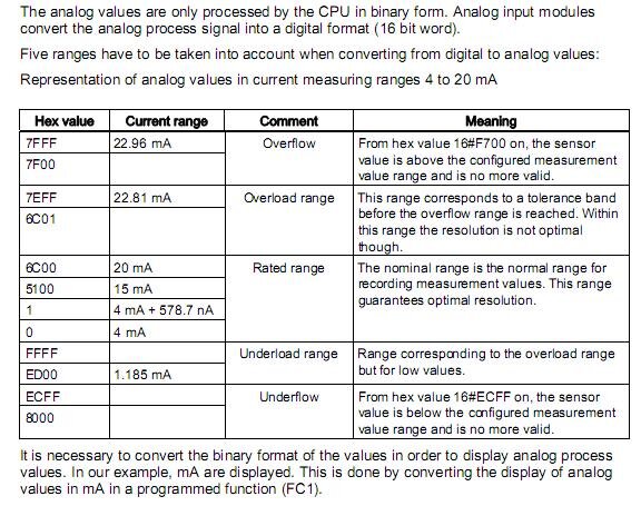
While working with a customer on a recent RSLogix 5000 project (now called Studio 5000), there was a need to protect some proprietary source code. In this particular case, DMC had developed a custom Add-On Instruction (AOI) to be used within the project that contained some unique logic that the client wished to protect. This is incredibly easy to do. Rockwell provides an easy tool for this that comes prepackaged with RSLogix. 
Since protecting intellectual property or touchy algorithms while opening up some of the code for modification or troubleshooting is pretty common, I thought I'd share some of the info I found and provide a few easy steps to locking down your code. Incidentally, while I'll walk you through configuring an AOI for source protection, you can use the same approach to protect routines as well.
Note that all of the information below can be found in various forms in two useful documents published by Rockwell Automation that I would highly recommend you download for reference:
Enabling Source Protection
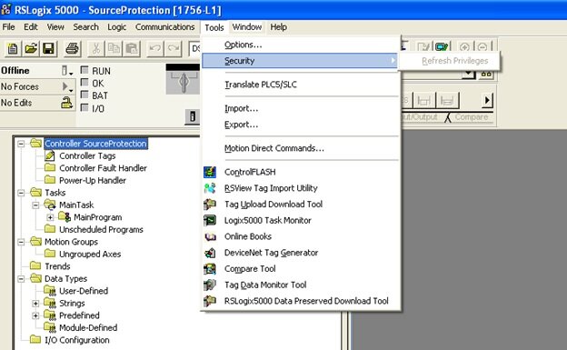
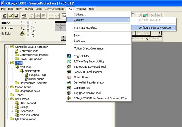
Out of the box, source code protection is not enabled in RSLogix 5000. So if you have never used it, chances are good that its never been activated. To check, open up the project you are working on and look under Tools >> Security. If you don't see an option for "Configure Source Protection," then you will need to enable it.

I would assume that you really only need to make a quick registry change, but its even easier than that as Rockwell provides a free tool you can download and run to take care of it for you. Allen Bradley provides some good instructions for the process that outline the different methods for different revs of RSLogix in Logix5000 Controllers Security. In my case, using rev 20, I needed to download Allen Bradley's Source Protection Tool. To find it, I started at their software download page and searched RSLogix Downloads. You should see it listed as "RSLogix 5000 Source Protection Tool." This is a quick download. After running, restart RSLogix and you should see a new option under Tools >> Security: Configure Source Protection.

Ok, after enabling, you can choose your newly available option and you will now be prompted to specify a Source Key File location. Go ahead and choose a location. If you don't have a source key file in the specified directory, you will be asked if you would like to create one. This source key file will contain your keys for any protection you establish. This file can be moved from computer to computer, or it can be built locally by adding the keys you create. Go ahead and create a new one; once you've done so, you're ready to lock down your code.

Protecting an AOI
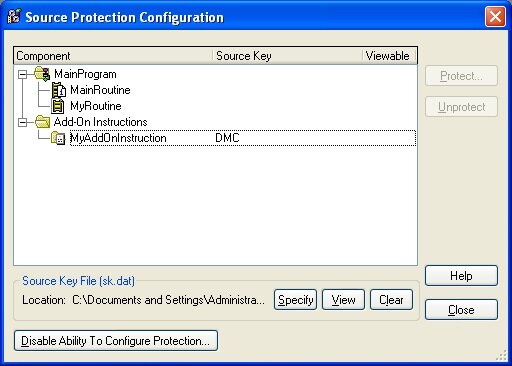
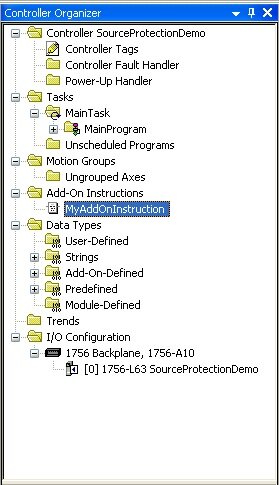
For a quick demo, I created a new project with a single Routine called 'MyRoutine' and a single AOI, 'MyAddOnInstruction.' Once you open up Source Protection Configuration from Tools >> Security, you will see that your programs and Add-On Instructions will be available. You can configure different keys and settings for each program and AOI, but lets just walk through configuration of 'MyAddOnInstruction.' Take a look and notice that there are currently no Source Keys defined.
 

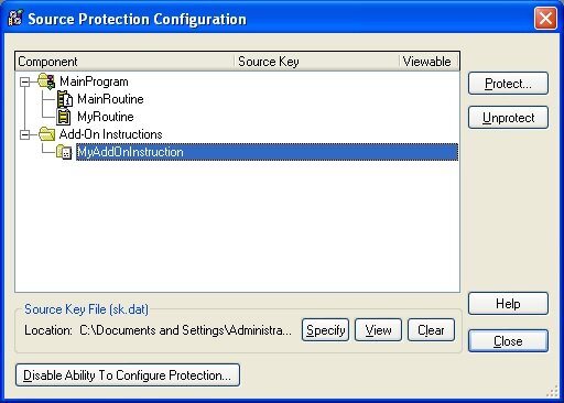
Select your AOI you would like to protect and choose "Protect." A Source Key dialog will open allowing you to select or create a source key to apply to your selected component (in this case, our AOI). I'm going to create a new one, "MyKey" and name it DMC. If you choose not to show the key (characters will not be shown on the screen) you will need to confirm the key a second time. I prefer to just see what I'm typing. You can also define a Source Key Name. This is really just a friendly name to associate with your key (think of user name::password, key name::key) that will be shown in the Source Protection Dialog to protect your key from prying eyes.
 

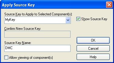
The checkbox in this dialog is worth discussing in a little more detail. You have two choices for the level of protection you are enabling. Leaving this checkbox unchecked will completely lock and hide the code source code from anyone without the key. Any one viewing the project (or any project containing this AOI) without the key will not be able to view, access, or edit the source code for the instruction. Selecting the checkbox will allow a user to view, but not to modify the source code, in effect making it read only. Of course with either selection, if you have the key, you have full access.
It should be noted that in addition to protecting any sensitive code, this can also be used as a method of source or version control and can be a great way to prevent unauthorized or unintended edits to sections of source code that have been validated or released.
Getting back to our walkthrough, let's go ahead and leave the checkbox unchecked and select OK. This will bring us back to the Source Protection Configuration dialog again, but you will now see that the key "DMC" has been added to our AOI and it is not selected as viewable for anyone without the key.

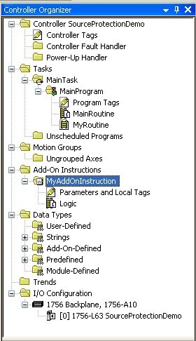
We're done here. Choose "Close" to exit the dialog and take a look at your project tree. You shouldn't notice any changes. You can still expand and see both Tags and Logic for the AOI we just protected. However, to see what it looks like to someone without the key, I'm going to save the project, exit RSLogix, and delete my key file. Now, after reopening the project we can see that I am not able to expand the AOI - there is no access to the Tags or Logic for the instruction.
       

If we dig a little deeper and open up the Source Protection Configuration dialog again, we will see that 'MyAddOnInstruction' is protected and has an unknown source key. Selecting the AOI and choosing "Protect" will bring us back to the Apply Source Key dialog. Attempting to apply a new source key other than the one we already created for this instruction will give an error and will not allow us to unlock it. However, I luckily grabbed a screenshot of the earlier showing me that I used the key 'MyKey.' Sure enough, entering this key will unlock the AOI and allow access to the source code again.
It is also worth taking the time here to export our AOI. Normally, an exported AOI will be saved in human readable text in an XML type format (try it!). However, when source protection has been enabled, this exported file is encrypted.
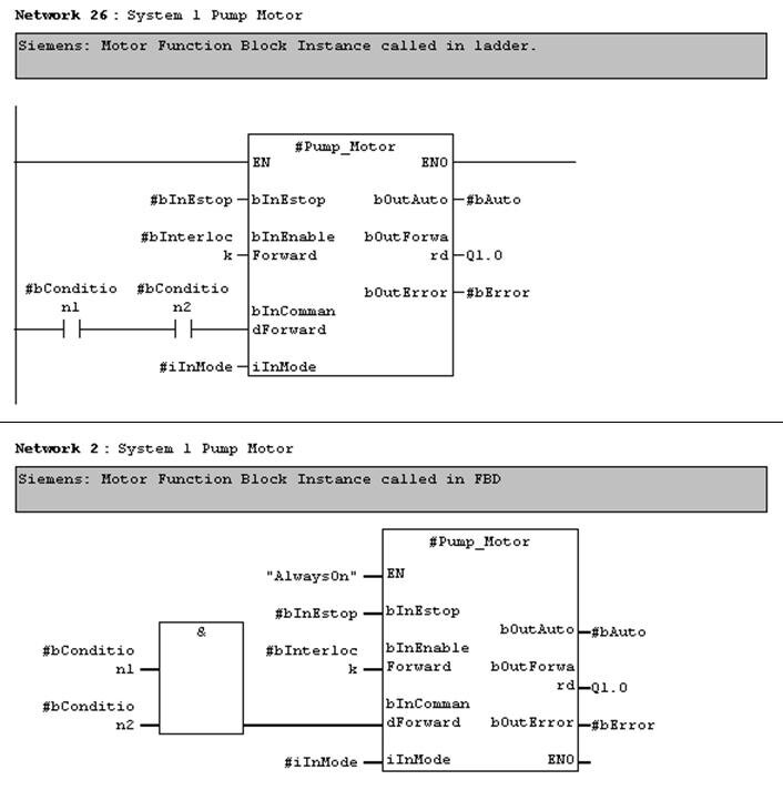
Before I wrap this up, I want to get back to one more point. I touched upon this earlier, but its worth mentioning that there are many reasons one may want to use Source Protection within their project. In addition to protecting proprietary code, it can also be a useful method of source control. A good example may be a custom motor implementation in a large project. Once development and testing has been completed on the instruction or routine, the code could be locked by the creator to prevent any accidental changes by others. By locking and then exporting to a library, other developers can then use the instruction and be guaranteed that the source code has not been modified.
This, combined with the version information available for each AOI and routine, can be a great way to manage a shared library of reusable code. DMC strives to make code as reusable as possible as a means to decrease development time (and cost), increase reliability, and provide for scalability and modularity. Combining this with versioning software such as SVN provides for an easy way to maintain a library for all our engineers to share.
Finally, a quick disclaimer about security. I personally haven’t delved into how encrypted or hidden this method of source code protection is, but it will probably serve for the majority of purposes. In the case of extremely valuable intellectual property, I would always strongly recommend consulting with experts before trusting that this is bullet proof. DMC has acquired a wealth of experience in the past few years protecting valuable information and has the experts available should this be the case.

Siemens vs Allen-Bradley: Function Blocks

iemens and Rockwell Automation are two giants competing in industrial automation technology today.  Rockwell (aka Allen-Bradley) seems to be more popular in the US market, but Siemens has a larger international customer base.  A cursory Google search will reveal that there is no lack of debate among automation professionals over which one is preferred.
On the higher end of their PLC lines, the programming environments to use are:
  •   Siemens - Step 7 Simatic Manager for S7-300 and 400 level PLCs
  •   Allen-Bradley (AB) - RSLogix 5000 for the Control Logix and Compact Logix PLCs 
As someone who uses both platforms regularly, I would like to compare one of the key differences between them - function blocks.

What's a function block?

Siemens uses the term Function Block (FB) for program routines that can have internal memory, as opposed to Function Calls (FC) that have only temporary internal memory.  Function blocks are a fundamental concept in the Siemens platform, which give them a significant advantage for large, modular applications.
In AB’s RSLogix 5000 version 16 and higher, reusable function blocks are called Add-On Instructions (AOI) and can be defined with interface parameters and local tags.  Since this feature was only added in 2007, it is often overlooked and doesn’t fit as seamlessly into the overall environment.
Why use function blocks, you ask?  You must read the DMC blog: "IEC 61131-3 Function Blocks - Unleash the Power!"
It is worth mentioning that both platforms adhere to the IEC-61131-3 standard, which means that function blocks are available and can be written in any of the standard's languages.

Interfacing to an instance of a function block

The way you interface to a function block is critical for program efficiency, readability, and development time.  The point of a reusable function block is to wrap up complex or repetitive code and make a simple and easy to use interface in order to use that code.  For example, when I visit a fast food drive-thru, I don’t need to tell them how to make a burger.  They have made billions before mine.  I just want to give my order, watch my burger come out the window, and then be on my way.
In AB:  Parameters in ladder have to be referenced independently from the function block call
If the function block instance is called in ladder, the input parameters can only be assigned with the block call if they are constants.  Variable inputs must be assigned to input parameters in preceding ladder rungs.  Outputs must be referenced in ladder rungs following the function block call.  If calling the function block instance in FBD (function block diagram), then variables can be directly assigned to input and output parameters.
Disadvantage:  More rungs of ladder to maintain.  If called in FBD instead, then there are restrictions on instance declaration (see below) and simple Boolean logic is more complicated because you must use the FBD function boxes instead of contacts and coils.

In Siemens:  Parameters are directly interfaced in both ladder and FBD
Function block instances that are called in ladder and FBD are essentially the same.  Even in ladder, variables can be assigned directly to input parameters.  Boolean input parameters can also be assigned to the result of ladder logic operations.  Function block outputs can be assigned directly to variables in the same rung of ladder.
Note that function block input and output parameters can also be accessed symbolically from other rungs in ladder logic (just like the AB example above), but Siemens has the additional advantage of directly assigning input and output parameters in the same rung as the function block call.
Advantage:  All input and output parameter assignment for a function block instance can be consolidated in one rung and not spread out on separate rungs or throughout the program.

Declaring an instance of a function block

In AB:  Limited to program tag file.  If using FBD, cannot reside in a UDT
Instances of AOIs are most commonly declared in the “Program Tags” file of a program folder.   Even for very modular programs, all function blocks are listed in this one common location.  Instances can be declared within UDTs (user-defined types), but not if you want to use them in the FBD environment.
Advantage:  Simplicity.  One location to look through for each program folder.

In Siemens:  Memory resides in an instance data block, but is declared within parent function blocks.
Most program logic, not just reusable logic, is located within function blocks.  “Parent” function blocks are assigned an instance data block.  All reusable function block instances can be declared within the parent function block’s static memory.
Advantage:  Modularity.  Instances are declared within the function block that they are called.

Summary 

In summary, Siemens seems to offer a little more flexibility in how function blocks are interfaced and instantiated.  We have seen, however, that both Allen Bradley and Siemens offer solutions for reusable function blocks on their higher-end PLCs.  Both Function Blocks in Siemens and Add-On Instructions in Allen Bradley will enhance the modularity and maintainability of your PLC program.  

Tuesday, April 14, 2015

Process Automation Handbook (PDF)

Book Description
To be an effective engineer in process automation requires knowledge of a range of disciplines: chemical engineering, instrumentation, electrical engineering, control theory, mathematics, computing and management. Other books in these areas are generic and few are oriented towards the needs of the chemical and process industry. Process Automation Handbook distills into a single coherent handbook all the essentials of process automation at a depth sufficient for most practical purposes. The knowledge needed to cope with the majority of process control and automation situations is focused on. In doing so, a number of balances have been struck between theory and practice, classical and modern, technology and technique, information and understanding. The reader is referred to more specialised texts after receiving a thorough grounding of each topic. Process Automation Handbook will be of value to engineers actively concerned with process control and automation in the chemical and process industries.


Table of Contents
Introduction
Instrumentation
Final Control Elements
Conventional Control Strategies
Process Control Schemes
Digital Control Systems
Control Technology
Management of Automation Projects
Maths and Control Theory
Plant and Process Dynamics
Simulation
Advanced Process Automation
Advanced Process Control

Download
You can download this book from any of the following links. If any link is dead please feel free to leave a comment.
Download here

keywords: Download free book, Download free PDF, free e-book

Copyright Disclaimer
This site does not store any files on its server. We only index and link to content provided by other sites. Please contact the content providers to delete copyright contents if any and email us, we'll remove relevant links or contents immediately.

Schneider Electric 2015 Global Automation Conference – Register today!


Powering Big Ideas Together: Register today and join Foxboro, Modicon, Triconex, and Schneider Electric users in Dallas. This year's conference is again offering dedicated sessions with access to experts where you will be able to discuss your most critical issues, share expertise and ...

innovatev4Gain insight: We'll challenge your thinking on how global trends will impact your business, and show you how our focus on innovation is evolving our technology roadmap to help you take advantage of every opportunity. 


collaborateCollaborate: Sessions will feature users sharing their practical experience-from challenges to value gained, plus tips and tricks to apply to your own operation. In the Marketplace, go one-on-one with Schneider Electric and our partners to discover the right solutions to suit your specific needs. 


learnLearn what's new: Find out what's new in our comprehensive portfolio of Control and Safety solutions, Telemetry and SCADA offerings, plus expanded services, advanced software, and field devices. We'll also introduce you to Schneider Electric's solutions for energy and resource management.


technical2Get Technical: Take part in in-depth technical training sessions to boost your knowledge and refine your expertise. See new product features first, discover proven capabilities, and find out "How To....". Earn Continuing Education Units (CEUs) in every workshop and tutorial session through our Learning Services. 


influence3Influence the Future: Share your challenges and suggestions in our product offer feedback sessions.


How to solve today's challenges safely, reliably and efficiently?

Get answers to your questions. Join us in Dallas!

chtrojlong
http://www.real-time-answers.com/global-automation

Siemens LOGO!Soft Comfort 8.0.0

Siemens AG , a global company in electronics and electrical engineering, and operates in the industry, energy and healthcare sectors, has announced the new release of LOGO!Soft Comfort 8.0, is software for programming simple Siemens LOGO! PLCs. Programming is done in one of two graphical programming languages - FBD (Function Block Diagram) or LAD (Ladder Diagram). Simulation and online monitoring is available. Suitable for use in small automation applications such as lighting, heating, ventilation, gate control etc.

Important new features:

- Graphical reference functions
- Status table including saving on PC (CSV format)
- Enhanced diagnostic options
- Improved commentaries
- Improved alignment of function blocks
- Import / export of port names
- Replacement of function blocks
- Virtual keyboard for message texts
- Astronomical clock with configurable on/off delay
- Macro (user-defined function) including commentaries, port name, password and parameter transfer
- Offline network simulation
- Supported operating systems Microsoft Windows: Microsoft Windows XP 32 Bit, Windows 7 (32 / 64 Bit, all versions), Windows 8 (32 / 64 Bit, all versions)
- Supported operating systems Mac OS X: Mac OS X 10.6 Snow Leopard; Mac OS x Lion; Mac OS x Mountain LION, Mac OS X Mavericks
- Supported operating systems LINUX: SUSE Linux 11.3 SP2, Kernel 3.0.76; runs on all Linux distributions on which Java 2 runs
- Program transfer over RS232 LOGO! programming cable. USB LOGO! programming cable and Ethernet
- All versions can be programmed (LOGO! 0BA0 to LOGO! 8)
- Single program and network mode
- Data exchange between LOGO! basic units via Drag & Drop
- Graphical representation of the network
- Automatic configuration of the Ethernet interface
- Automatic identification of the accessible nodes in the network
- Enhanced usability
- Enhanced graphical user interface (GUI)

Last but not least, LOGO! Soft Comfort provides professional documentation with all of the necessary project information such as switching programs, comments, and parameter settings.

About Siemens

Siemens AG (Berlin and Munich) is a global technology powerhouse that has stood for engineering excellence, innovation, quality, reliability and internationality for more than 165 years. The company is active in more than 200 countries, focusing on the areas of electrification, automation and digitalization.

Name: SIEMENS LOGO!Soft Comfort
Version: 8.0.0
Home:
www.siemens.com

Interface: english
OS: Windows / Linux / MacOsx
Size: 338.2 mb

Download From NitroFlare
http://www.nitroflare.com/view/93C485A5D2A3CD9/enSLoSC800.rar

Download From Uploaded
http://uploaded.net/file/h5rhypie/enSLoSC800.rar

Download From Rapidgator
http://rapidgator.net/file/613b85c2e5c6a540650f603fd5939439/enSLoSC800.rar.html


PLC programming cables for several brands

Most PLC's can be programmed from a PC via a serial cable. Unfortunately, many of these cables have a non standard layout. De cables shown here can be bought from the regular sales channels, but it is often much cheaper to solder them yourself.

Siemens PLC's

Most programming of Siemens S5 PLC's is done using a special RS232 to TTY converter. The S7 series are programmed using a RS232 to MPI bus converter. The easiest thing to do is buy these special cables from your local Siemens supplier. The operator terminals however can be programmed using a normal serial cable. The following cable can be used to program the OP series of operator displays.
Programming cable for OPxx display series

Idec / Izumi PLC's

Idec / Izumi PLC series FA2, FA2J and FA3J all require a special communication adaptor for programming. This communication link adaptor (CLA) is a small box that converts the RS232 electrical signals into a compatible level for the PLC. The cable to connect the PC to a CLA uses a DB25 connector at the PLC side. The layout for a cable with a DB9 connector at the PC side is shown here.
DB9 Programming cable for Idec / Izumi FA PLC series
DB9 Programming cable for Idec / Izumu FA PLC series

Z-World microcontrollers

Z-World is an American company specialized in developing microcontroller boards based on the Z180 and Rabbit series micro controllers. Where PLC's are often used in single piece environments, micro controllers are mainly present in the OEM world where multiple controllers are needed.
The main difference in programming a PLC is that most microcontrollers, including those from Z-World, are programmed in C. The Z-World programming package runs on a normal PC and the connection with the controller is made using a serial cable. This cable needs a DB9 connector at one and, and a RJ14 plug at the other. The pin out of a programming cable is shown here.
DB9 Programming cable for Z-World PK microcontroller series
#