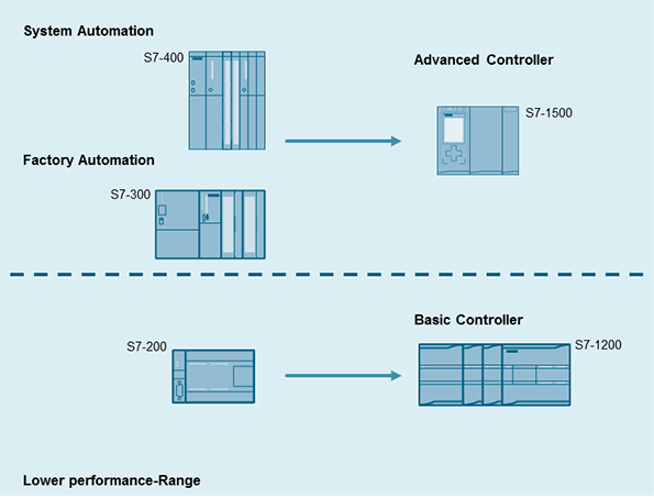
In this lesson we will learn how to write a PLC program using an "S7 300” PLC and “STEP 7” software.
We have two pumps which are being used to transfer two separate liquids into this tank.Inside the tank there are two level switches installed in the lower and upper parts of the tank respectively.
There is also an electrically powered mixer inside the tank which starts working for a defined period of time, mixing the two liquids together after the tank has filled.
We also have a discharge valve in the bottom of the tank which controls the draining of the liquid from the tank.
When the level of the liquid drops to the level of the switch's position the contact closes, sending a 24 volt DC signal to the PLC input.
We want to write the program so that when the level of the liquid reaches this minimum, the pumps will be activated and begin filling the tank with the liquids.
The pumps continue filling the tank until the level reaches its maximum at the higher level switch. When this happens the open contacts in the switch will be closed and another 24 volt signal will be sent to the PLC input telling us that the tank is full.
When this signal has been sent, first the pumps should shut down so that no more liquid enters the tank, and then this mixer should be turned on.
We want the mixer to operate for seven seconds, mixing the liquids that have been pumped into the tank.
After seven seconds the mixer should automatically shut down and this discharge valve should open.
With the valve open the liquid will be discharged from the tank and transferred to another location within the factory to be processed.
When the level of the liquid in the tank drops to the minimum set level of the lower switch, the switch contacts will close again thus starting a repeat of the cycle!
This is the third video of “star-delta starter PLC program and wiring video series”. In this video you’re going to learn the wiring of star-delta starter.
The basic concept of star-delta starter is to first run the motor in the star connection for a few seconds to reduce the start current. Then when the motor has gained sufficient speed, change the winding connections to delta.
PLC Training_Star-Delta Starter PLC program and Wiring_ Part 1:
https://youtu.be/skcaCBxyNSk
PLC Training_ Star-Delta Starter PLC Program and Wiring_Part 2:
http://youtu.be/FOKSkCR6JQY
PLC Training_ Star-Delta Starter PLC Program and Wiring_Part 3:
https://youtu.be/aEkQuqEdlVA
PLC Training_ Star-Delta Starter PLC Program and Wiring_Part 4:
https://youtu.be/SOZwFUzTQsU
PLC Training_ Star-Delta Starter PLC Program and Wiring_Part 5:
https://youtu.be/qA3Yg5CS-F8
PLC Training_ Star-Delta Starter PLC Program and Wiring_Part 6:
https://youtu.be/J9RMP8l3vDA
PLC Training_ Star-Delta Starter PLC Program and Wiring_Part 7:
https://youtu.be/0q-CDJinDVw
PLC Training_ Star-Delta Starter PLC Program and Wiring_Part 8:
https://youtu.be/nqlEK_ERTxk
PLC Training_ Star-Delta Starter PLC Program and Wiring_Part 9:
https://youtu.be/fiPSMyFIiFY


