No Copy


No Right Click

Selamat Datang di Situs Belajar PLC dan SCADA

Blog gratis yang menyajikan berita seputar PLC dan SCADA.

Microsoft Windows 10

Berita seputar Microsoft Windows 10. Membahas berbagai informasi mengenai Microsoft windows terbaru.

Apple OSX

Artikel yang membahas tentang OSX terbaru dari Apple tentu sangat menarik untuk dibaca. Tak kalah serunya jika kita paham mengenai tips dan trik yang ada didalamnya.

Photography

Photography asik dan menarik jika kita mengetahuinya lebih dalam. Disini kita bisa melihat berbagai hal dari sudut pandang photo. Menarik untuk dipahami.

Saturday, August 29, 2015

What can a PLC do? Why do we use them?

The meaning of PLC…

PLC” means “Programmable Logic Controller”, that’s clear. The word “Programmable” differentiates it from the conventional hard-wired relay logic. It can be easily programmed or changed as per the application’s requirement. The PLC also surpassed the hazard of changing the wiring.
The PLC as a unit consists of a processor to execute the control action on the field data provided by input and output modules. In a programming device, the PLC control logic is first developed and then transferred to the PLC.
So, what can a PLC actually do?
  1. It can perform relay-switching tasks.
  2. It can conduct counting, calculation and comparison of analog process values.
  3. It offers flexibility to modify the control logic, whenever required, in the shortest time.
  4. It responds to the changes in process parameters within fractions of seconds.
  5. It improves the overall control system reliability.
  6. It is cost effective for controlling complex systems.
  7. It trouble-shoots more simply and more quickly
  8. It can be worked with the help of the HMI (Human-Machine Interface) computer
There are many other things this little ‘mean’ thing can do, but one thing I’m sure – that PLCs are irreplaceable in many industry applications and control projects.
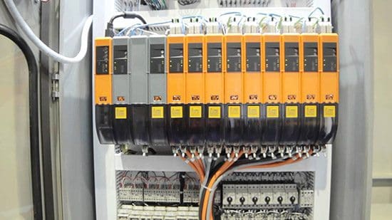
Here is an example of wired ABB’s AC500 programmable logic controllers.
Wired ABB's PLCs
Figure 1 – Wired ABB’s PLCs (photo credit: us.profinet.com)

Basic block diagram

Figure 1 shows the basic block diagram of a common PLC system.
Block diagram of a PLC
Figure 2 – Block diagram of a PLC

As shown in the above figure, the heart of the “PLC” in the center, i.e., the Processor or CPU (Central Processing Unit).
  • The CPU regulates the PLC program, data storage, and data exchange with I//O modules.
  • Input and output modules are the media for data exchange between field devices and CPU. It tells CPU the exact status of field devices and also acts as a tool to control them.
  • A programming device is a computer loaded with programming software, which allows a user to create, transfer and make changes in the PLC software.
  • Memory provides the storage media for the PLC program as well as for different data.

Size of the PLC system

Usually they are classified on the basis of their size:
  • A small system is one with less than 500 analog and digital I/Os.
  • A medium system has I/Os ranging from 500 to 5,000.
  • A system with over 5,000 I/Os are considered large.

Components of the PLC system

CPU or processor: The main processor (Central Processing Unit or CPU) is a microprocessor-based system that executes the control program after reading the status of field inputs and then sends commands to field outputs.
I/O section: I/O modules act as “Real Data Interface” between field and CPU. The PLC knows the real status of field devices, and controls the field devices by means of the relevant I/O cards.
Programming device: A CPU card can be connected with a programming device through a communication link via a programming port on the CPU.
Operating station: An operating station is commonly used to provide an “Operating Window” to the process. It is usually a separate device (generally a PC), loaded with HMI (Human Machine Software).

PLC Configurations

There are two basic configurations that commercial manufacturers offer:
1. Fixed Configuration
Fixed PLC configuration

2. Modular Configuration
Modular type PLC 'SLC 500'
Modular type PLC ‘SLC 500’ (photo credit: ab.rockwellautomation.com)

PLC Applications (VIDEOs) //

Real world applications


An Application for Industrial Process Control


PLC Bottling Application

PLC application color mixing


PLC Suited To Bottling Line Application

5 guides to study PLCs //

  1. PLC – Programmable Logic Controller – Hugh Jack
  2. PLC Programming – OMRON
  3. PLC – Theory and Implementation – L.A. Bryan; E.A. Bryan
  4. Industrial Training – SCADA System and PLC – Mr. Sonu Kumar Yadav

References //
  • Industrial Automation Pocket Book – IDC Technologies
  • Overview of Programmable Overview of Programmable Logic Controllers – Dr. Fernando Rios-Gutierrez
Comparison of Soft Starting and Frequency Converter Motor Starting

Soft starting

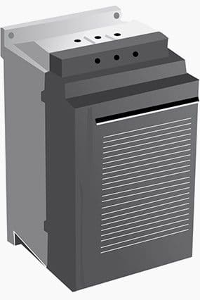
A soft starter is, as you would expect, a device which ensures a soft starting of a motor.
A soft starter has different characteristics to the other starting methods. It has thyristors in the main circuit, and the motor voltage is regulated with a printed circuit board. The soft starter makes use of the fact that when the motor voltage is low during start, the starting current and starting torque is also low.
Motor soft starter
Motor soft starter

Advantages //

Soft starters are based on semiconductors. Via a power circuit and a control circuit, these semi-conductors reduce the initial motor voltage.
This results in lower motor torque.
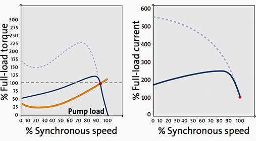
During the starting process, the soft starter gradually increases the motor voltage, thereby allowing the motor to accelerate the load to rated speed without causing high torque or current peaks.
Soft-starting curve - Synchronous speed - Full load torque (left) and Full load current (right)
Soft-starting curve – Synchronous speed – Full load torque (left) and Full load current (right)

Soft starters can also be used to control how processes are stopped. Soft starters are less expensive than frequency converters.
Another feature of the soft starter is the soft stop function, which is very useful when stopping pumps where the problem is water hammering in the pipe system at direct stop as for star-delta starter and direct-on-line starter.

Drawbacks //

They do, however, share the same problem as frequency converters: they may inject harmonic currents into the system, and this can disrupt other processes. 
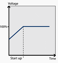
Voltage ramp for soft starter. Run-up time is around 1 sec.

The starting method also supplies a reduced voltage to the motor during start-up.
The soft starter starts up the motor at reduced voltage, and the voltage is then ramped up to its full value. The voltage is reduced in the soft starter via phase angle. In connection with this starting method current pulses will not occur. Run-up time and locked-rotor current (starting current) can be set.

Electric Motor Soft Start 60HP (VIDEO)

Part 1


Part 2


Frequency converter starting

Frequency converters are designed for continuous feeding of motors, but they can also be used for start-up only.
The frequency converter is sometimes also called VSD (Variable Speed Drive), VFD (Variable Frequency Drive) or simply Drives, which is probably the most common name.
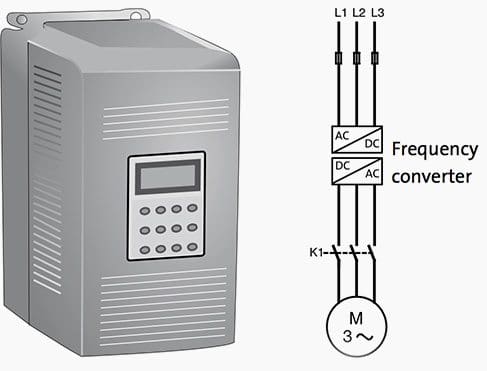
The drive consists primarily of two parts, one which converts AC (50 or 60 Hz) to DC and the second part which converts the DC back to AC, but now with a variable frequency of 0-250 Hz. As the speed of the motor depends on the frequency this makes it possible to control the speed of the motor by changing the output frequency from the drive and this is a big advantage if there is a need for speed regulation during a continuous run.
As stated above, in many applications a drive is still only used for starting and stopping the motor, despite the fact that there is no need for speed regulation during a normal run. Of course this will create a need for much more expensive starting equipment than necessary.
By controlling the frequency, the rated motor torque is available at a low speed and the starting current is low, between 0.5 and 1.0 times the rated motor current, maximum 1.5 x In.
Another available feature is softstop, which is very useful, for example when stopping pumps where the problem is water hammering in the pipe systems at direct stop. The softstop function is also useful when stopping conveyor belts from transporting fragile material that can be damaged when the belts stop too quickly.
It is very common to install a filter together with the drive in order to reduce the levels of emission and harmonics generated.
Frequency converter and its line diagram

Advantages //

The frequency converter makes it possible to use low starting current because the motor can produce rated torque at rated current from zero to full speed. Frequency converters are becoming cheaper all the time.
As a result, they are increasingly being used in applications where soft starters would previously have been used.
Frequency converter curve – Synchronous speed – Full load torque (left) and Full load current (right)

Drawbacks //

Even so, frequency converters are still more expensive than soft starters in most cases; and like soft starters, they also inject harmonic currents into the network.

What is a drive? (VIDEO)


VLT drives in large desalination plant (VIDEO)


VLT drives control cooling tower fans (VIDEO)


References //

PLC Implementation Of Forward/Reverse Motor Circuit With Interlocking

Forward/Reverse Motor Interlocking

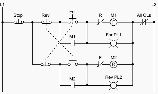
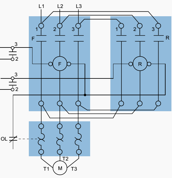
Figure 1 illustrates a hardwired forward/reverse motor circuit with electrical and push buttoninterlockings. Figure 2 shows the simplified wiring diagram for this motor. The PLC implementation of this circuit should include the use of the overload contacts to monitor the occurrence of an overload condition.
The auxiliary starter contacts (M1 and M2) are not required in the PLC program because the sealing circuits can be programmed using the internal contacts from the motor outputs.
Hardwired forward/reverse motor circuit
Figure 1 – Hardwired forward/reverse motor circuit

Low-voltage protection can be implemented using the overload contact input so that, if an overload occurs, the motor circuit will turn off. However, after the overload condition passes, the operator must push the forward or reverse push button again to restart the motor.
Forward/reverse motor wiring diagram
Figure 2 – Forward/reverse motor wiring diagram

For simplicity, the PLC implementation of the circuit in Figure 1 includes all of the elements in the hardwired diagram, even though the additional starter contacts (normally closed R and F in the hardwired circuit) are not required, since the push button interlocking accomplishes the same task.
In the hardwired circuit, this redundant interlock is performed as a backup interlocking procedure.
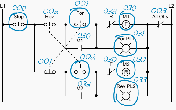
Real inputs and outputs to the PLC
Figure 3 – Real inputs and outputs to the PLC

Figure 3 shows the field devices that will be connected to the PLC. The stop push button has address 000, while the normally open sides of the forward and reverse push buttons have addresses 001 and 002, respectively. The overload contacts are connected to the input module at address 003.
The output devices – the forward and reverse starters and their respective interlocking auxiliary contacts – have addresses 030 and 032. The forward and reverse pilot light indicators have address 031 and 033, respectively.
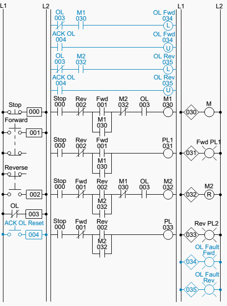
Additionally, the overload light indicators have addresses 034 and 035, indicating that the overload condition occurred during either forward or reverse motor operation. The addresses for the auxiliary contact interlocking using the R and F contacts are the output addresses of the forward and reverse starters (030 and 032). The ladder circuit that latches the overload condition (forward or reverse) must be programmed before the circuits that drive the forward and reverse starters as we will explain shortly. Otherwise, the PLC program will never recognize the overload signal because the starter will be turned off in the circuit during the same scan when the overload occurs.
If the latching circuit is after the motor starter circuit, the latch will never occurbecause the starter contacts will be open and continuity will not exist.
Table 1 shows the real I/O address assignment for this circuit. Figure 4 shows the PLC implementation, which follows the same logic as the hardwired circuit and adds additional overload contact interlockings.

Table 1 – I/O address assignment

I/O Address
Module TypeRackGroupTerminalDescription
 Input000Stop PB (wired NC)
001Fowrward PB (wired NO)
002Reverse PB (wired NO)
003Overload contacts
 Input004Acknowledge OL/Reset PB
 Output030Motor starter M1 (FWD)
031Forward PL1
032Motor starter M2 (REV)
033Reverse PL2
 Output034Overload condition FWD
035Overload condition REV
036
037

Note that the motor circuit also uses the overload input, which will shut down the motor. The normally closed overload contacts are programmed as normally open in the logic driving the motor starter outputs. The forward and reverse motor commands will operate normally if no overload condition exists because the overload contacts will provide continuity.
However, if an overload occurs, the contacts in the PLC program will open and the motor circuit will turn OFF. The overload indicator pilot lights (OL Fault Fwd and OL Fault Rev) use latch/unlatch instructions to latch whether the overload occurred in the forward or reverse operation.
PLC implementation of the circuit in Figure 1
Figure 4 – PLC implementation of the circuit in Figure 1

Again, the latching occurs before the forward and reverse motor starter circuits, which will turn off due to the overload. An additional normally open acknowledge overload reset push button, which is connected to the input module, allows the operator to reset the overload indicators. Thus, the overload indicators will remain latched, even if the physical overloads cool off and return to their normally closed states, until the operator acknowledges the condition and resets it.
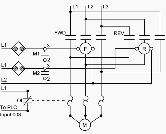
Figure 5 illustrates the motor wiring diagram of the forward/reverse motor circuit and the output connections from the PLC. Note that the auxiliary contacts M1 and M2 are not connected.
Forward/reverse motor wiring diagram
Figure 5 – Forward/reverse motor wiring diagram

In this wiring diagram, both the forward and reverse coils have their returns connected to L2 and not to the overload contacts. The overload contacts are connected to L1 on one side and to the PLC’s input module on the other (input 003). In the event of an overload, both motor starter output coils will be dropped from the circuit because the PLC’s output to both starters will be OFF.

Control circuit for forward and reverse motor (VIDEO)

Cant see this video? Click here to watch it on Youtube.
Reference: Resource: Introduction-to-PLC-Programming – www.globalautomation.info

4 Steps To Follow During Commissioning of a PLC System

PLC programs are never final…

Yes, PLC programs are never final, it is always possible to make corrections and subsequent adaptations to new system according the customer requirements. Even during commissioning,program changes are often necessary. The commissioning of a system can be divided into four steps:
  1. Checking the hardware
  2. Transferring and testing the software
  3. Optimisation of the software
  4. Commissioning of the entire system

1. Checking the hardware

Each sensor, switch and button is connected to a specific input and each actuator to an output. During engineering process addresses and wires must not be mixed up. Also, the sensors and actuator placing should be checked (that they are where they have to be in the automated system).
During checking procedure, the outputs are set in a test mode. The actuators must then meet the specified requirements (functions). If changes are made, then the documentation (allocation list, drawings, etc) must also be updated to respond to reality.
PLC hardware
PLC hardware (photo credit: BR Automation)

1.1 Testing inputs and outputs

Input devices, e.g. switches, can be manipulated to give the open and closed contact conditions and the corresponding LED on the input module observed. It should be illuminated when the input is closed and not illuminated when it is open.
Failure of an LED to illuminate could be because the input device is not correctly operating, there are incorrect wiring connections to the input module, the input device is not correctly powered or the LED or input module is defective. For output devices that can be safely started, push buttons might have been installed so that each output can be tested.

2. Transferring and testing of software

Prior to commissioning, all available off-line and virtual PLC program testing tools should be used intensively to find program faults. For example, such test tool is in STEP 7 as subprogram S7-PLCSIM. It simulates the work of a PLC (virtual PLC) and allows the user written PLC program to be tested.
Following this, the program is transferred to a central processing unit in the virtual PLC. The entire program is executed without using the real PLC.
The user has to simulate the input signal changes and verify how the outputs react to it. Some PLCs offer simulation in a real PLC: the entire program is executed in a PLC without the real inputs and outputs being connected. Processing of the PLC outputs thus only takes place in the PLC image table. The physical PLC I/Os are not updated to/from the PLC I/O images.
Therefore this eliminates the risk of damaging machines or system parts.
After this, the individual user program parts and system functions are tested: manual operation, setting, individual monitoring programs etc. and finally the interaction of the program parts with the help of the main program.
The system can and should be commissioned step-by-step. Important aspects of commissioning and fault detection are the test functions of the programming system, such as the single-step mode or the setting of stop points. The single-step mode in particular is of importance, whereby theprogram in the PLC memory is executed line-by-line or step-by-step. In this way, any program faults which may occur in the program can be immediately localized.

3. Optimisation of the software

User programs can almost always be improved after the first test run. It is important that any corrections or modifications are made not just in the PLC user program, but are also taken into account in the documentation.

4. Commissioning of the entire system

This already occurs in part during the testing and optimization phase. Once the final status of thePLC user program and the documentation is established, all the controller functions (in accordance with the automation task) need to be executed step-by-step again.
If no faults occur by the entire system commissioning, then the system is ready to be handed over to the customer.
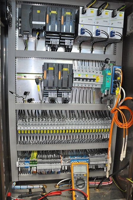
PLC panel during commissioning
PLC panel during commissioning (photo credit: megawatts.com.sg)
#