Tags are the method for assigning and referencing memory locations in Allen Bradley Logix5000 controllers. No longer are there any physical addresses such as N7:0 or F8:7 which use symbols to describe them. These have been replaced with tags which are a pure text based addressing scheme. This is a departure from the more conventional ways of programming PLC’s, which includes Allen Bradley’s earlier line of PLC5 and SLC 500 controllers.
One of the hardest transitions from the older systems is realizing how the tag database works. The person with experience in Allen Bradley systems will recognize many of the instructions and be at home with the editor in RSLogix 5000. Understanding the tag database is the first major hurdle in becoming comfortable with the ControlLogix and CompactLogix systems. So let’s dig in and get started.
The Way We Used To Be
Earlier Allen Bradley PLCs programmed with RSLogix 5 and RSLogix 500 software had data files to store I/O and other internal values. These different data files could only hold one data type. A data type defines the format and the size of the stored value.
Default Data Files
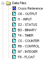
Data File Descriptions
File # | Type | Description |
O0 | Output | This file stores the state of output terminals for the controller. |
I1 | Input | This file stores the state of input terminals for the controller. |
S2 | Status | This file stores controller operation information useful for troubleshooting controller and program operation. |
B3 | Bit | This file stores internal relay logic. |
T4 | Timer | This file stores the timer accumulator and preset values and status bits. |
C5 | Counter | This file stores the counter accumulator and preset values and status bits. |
R6 | Control | This file stores the length, pointer position, and status bits for control instructions such as shift registers and sequencers. |
N7 | Integer | This file is used to store bit information or numeric values with a range of -32767 to 32768. |
F8 | Floating Point | This file stores a # with a range of 1.1754944e-38 to 3.40282347e+38. |
While this method made it easy for using instructions, it provided a challenge for logically grouping different data types together according to function. For instance, in machine control, a motor may have a start, stop, speed and alarm code each with its own data type. Thus, the data was “scattered” throughout the data files.
File # | Name | Data Type |
I1 | Start | Input |
I1 | Stop | Input |
F8 | Speed Setpoint | Floating Point |
N7 | Alarm Code | Integer |
Comparing the Old and New
The Logix5000 controllers have done away with data files and in its place is the tag database. The tag database organizes memory locations in one place. Each tag is assigned its own data type. The table below shows the association between the current data types and the older systems with data files.
RSLogix 5 / 500 | RSLogix 5000 | ||
File # | Type | ||
O0 | Output | Input and output modules, when configured, automatically create their own tags like Local:0:I.Data.0 | |
I1 | Input | ||
S2 | Status | Use the GSV and SSV instructions to get status information such as the CPU time, module states and scan times. | |
B3 | Bit | Assign the Boolean (BOOL) data type to the tag. | |
T4 | Timer | Assign the TIMER data type to the tag. | |
C5 | Counter | Assign the COUNTER data type to the tag. | |
R6 | Control | Assign the CONTROL data type to the tag. | |
N7 | Integer | Assign the double integer (DINT) data type to the tag. | |
F8 | Floating Point | Assign the REAL data type to the tag. | |
Creating a Tag
One way to create a new tag is right click on the Controller Tags in the Controller Organizer and select New Tag. Even faster is the Ctrl+W hot key.
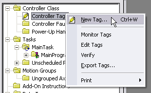
The following dialog box pops up.
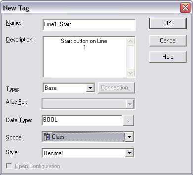
The Name given to the tag has the following rules:
- only alphabetic characters (A-Z or a-z), numeric characters (0-9), and underscores (_)
- must start with an alphabetic character or an underscore
- no more than 40 characters
- no consecutive or trailing underscore characters (_)
- not case sensitive
While tags are not case sensitive, it is good practice to mix cases for readability. It is much easier to read Line1_Start then LINE1START or line1start.
In addition, the tag database list sorts alphabetically. Therefore, it is best to use similar starting characters when you want tags to be together in the monitor list.
Tags Named for Grouping | Tags Not Named for Grouping | |
Level_High | High_Level | |
Level_Low | Insert_Nut | |
Insert_Nut | Knife_Stop | |
Knife_Stop | Low_Level |
Use the Description field for a longer description of the tag. It is best to keep names short yet not cryptic. Tag names are downloaded and stored in the controller but the description is not as it is part of the documentation of the project.
The tag Type defines how the tag operates in the project
Base | A tag that actually defines the memory where the data is stored |
Alias | A tag that represents another tag |
Produced | Send data to another controller |
Consumed | Receive data from another controller |
Alias tags mirror the base tag to which they refer. When the base tag value changes so does the alias tag. Use aliases in the following situations:
- program logic in advance of wiring diagrams
- assign a descriptive name to an I/O device
- provide a more simple name for a complex tag
- use a descriptive name for an element of an array
Produced and consumed tags make it possible to share tags between controllers in the same rack or over a network. This article does not cover this aspect.
Select a Data Type for the tag by typing it in or by clicking on the ellipsis button and selecting it from the list. A data type is a definition of the size and layout of memory allocated for the created tag. Data types define how many bits, bytes, or words of data a tag will use.
The term Atomic Data Type refers to the most basic data types. They form the building blocks for all other data types.
Data Type | Abbreviation | Memory bits | Range |
Boolean | BOOL | 1 | 0-1 |
Short Integer | SINT | 8 | -128 to 127 |
Integer | INT | 16 | -32,768 to 32,767 |
Double Integer | DINT | 32 | -2,147,483,648 to 2,147,483,647 |
Real Number | REAL | 32 | +/-3.402823E38 to +/-1.1754944E-38 |
Logix5000 controllers are true 32-bit controllers, meaning the memory words are 32-bits wide. No matter what, a tag always reserves 32 bits of memory even if it is a Boolean or integer data type. For this reason, it is best to use a DINT when dealing with integers. Furthermore, a Logix5000 controller typically compares or manipulates values as 32-bit values (DINTs or REALs).
A Logix5000 controller lets you divide your application into multiple programs, each with its own data. The Scope of the tag defines if a tag is global (controller tags) and therefore available to all programs or local (program tags) to a select program group. Pay careful attention to this field as creating it in the wrong area may lead to some confusion later on as to its location.
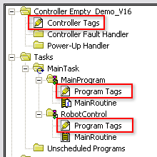
Controller Tags are available to all programs. You cannot go wrong using controller scoped tags unless you easily want to copy and paste programs. A tag must be controller scoped when used in a Message (MSG) instruction, to produce or consume data and to communicate with a PanelView terminal.
Program Tags are isolated from other programs. Routines cannot access data that is at the program scope of another program. Having program tags make it easy to copy/paste programs and not have to worry about conflicting tag names. Make sure though that no controller tags are named the same as program tags.
Style is the form in which to display the tag by default. The following table provides you with information on the base and notation used for each style.
Style | Base | Notation |
Binary | 2 | 2# |
Decimal | 10 | |
Hexadecimal | 16 | 16# |
Octal | 8 | 8# |
Exponential | 0.0000000e+000 | |
Float | 0.0 |
Edit and Monitor Tags
To edit existing tags select the Logic > Edit Tags menu item. A spread sheet like view lets you create and edit tags.
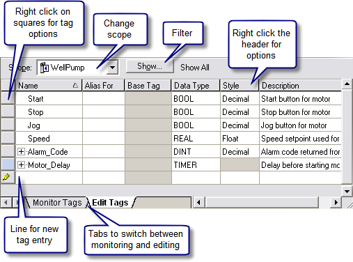
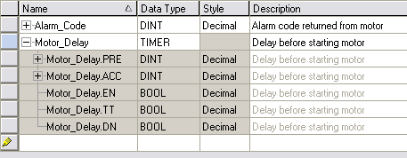
Clicking the + sign next to a tag reveals its structure. For a DINT tag this is the 32 individual bits that make up the tag which will not be of interest if you are using the tag as a number rather then individual bits. If you do wish to use the individual bits then you can address them in this way with the tag name followed by a period and then the bit position (e.g. MyTag.5). Shown below is the expanded structure for a TIMER. Notice it is made of two DINTs and three BOOLs. In this case, the Booleans are packed into one DINT and therefore a timer uses three DINTs of memory.
An Easier Way to Create Tags
The easiest way to create tags is on the fly while programming. When an instruction is first used a “?” will indicated the need for a tag. There are three options at this point:
- Double click on the “?” and select an existing tag from the drop down box.
- Right click on the “?” and select new tag.
- Double click on the “?” and type in the tag name. If it does not all ready exist, then right click on the tag name and select Create “NewTagName”. Be careful with this method not to use spaces or special characters.
The nice thing about all these methods is that RSLogix5000 will automatically fill in the correct data type according to the instruction used.
Another quick method is to drag and drop an existing tag to a new instruction. Make sure to click on the tag name rather then the instruction.

Conclusion
These are the basics of tags. The advantages are:
- Tags, if done right, create a level of documentation that is stored in the PLC.
- The software does an automatic housekeeping of memory locations. There’s no more worrying about physical addressing and memory conflicts.
- Structures can be more easily put together based on function rather then data type.
Advance subjects include arrays, user defined data types (UDT) and Add-On Instructions. Hopefully, you will continue to learn more about the power of tags. There is no doubt that if you grasp the principles presented here you will be well on your way to using and troubleshooting any Logix5000 controller.


0 Comments:
Post a Comment