This is video tutorial about RSLogix from Rockwell. Video Sample.
If you interesting, please visit http://www.youtube.com/RonBeaufort
Just another Blog about Programmable Logic Controller & SCADA.
Blog gratis yang menyajikan berita seputar PLC dan SCADA.
Berita seputar Microsoft Windows 10. Membahas berbagai informasi mengenai Microsoft windows terbaru.
Artikel yang membahas tentang OSX terbaru dari Apple tentu sangat menarik untuk dibaca. Tak kalah serunya jika kita paham mengenai tips dan trik yang ada didalamnya.
Photography asik dan menarik jika kita mengetahuinya lebih dalam. Disini kita bisa melihat berbagai hal dari sudut pandang photo. Menarik untuk dipahami.
Question
Is a battery for EEPROM memory backup required when using an EEPROM Memory Cassette with C200HS or C200HX/HG/HE Programmable Controllers?
Answer
Question
Can a single sensor output be connected to multiple Programmable Controllers Input Units in parallel?
Answer
1.The sum of the total input currents of the Input Units must be below the maximum switching capacity of the transistor in the sensor output.
2.The leakage current from the transistor in sensors output may prevent the inputs to the Input Units from turning OFF. You must be sure that the inputs will turn OFF when sensors output turns OFF.
As a condition for this, the input impedance of the Input Unit and the leakage current can be used to calculate the voltage when the sensor output is OFF. You must be sure that this voltage is less than the OFF voltage of the Input Unit.
3.Sensors signal must be long enough to be detected by the Input Units. The ON/OFF signal from Sensors must be longer than the Programmable Controllers' scan time.
The following formula must be satisfied by the above conditions.
Sum of all leakage currents < Maximum switching capacity of transistor in sensors output
The leakage currents of the pulse output for the transistor in the sensor pulse output when it is turned OFF will not cause the Programmable Controllers input circuit to turn OFF (i.e., satisfies the following condition).
Leakage current of output transistor when OFF x Input impedance of input circuit on Programmable Controllers < Voltage at which Programmable Controllers input turns OFF
The Programmable Controllers must be able to detect the sensor’s ON/OFF signal.
Shorter of ON or OFF signal for sensor/pulse output > Length of one Programmable Controllers scan
Question
Can a single-phase motor be controlled by a 3G3EV Inverter with a single-phase 100-V input?
Answer
The Inverter creates a virtual alternating current with high-speed switching.
If the Inverter is connected to a single-phase capacitor-start induction motor, the capacitor will overheat and burn due to repetitive charging and discharging, so do not connect to this kind of motor.
In addition, if the Inverter is connected to a split-phase-start induction motor or repulsion-start induction motor, the motor's internal centrifugal switch will not operate, and the starting coil may overheat, so do not connect these kinds of motors. Use a three-phase motor.
Question
What products are recommended as substitutes for the C200H-CPU01 Programmable Controller?
Answer
Selection Precautions:
1. A Power Supply Unit must be purchased (e.g., the C200HW-PA204).
2. Check the Memory Unit that was used with the C200H-CPU01.
C200HE-CPU11: 3.2 Kwords (built-in RAM)
C200HE-CPU32/42: 7.2 Kwords (built-in RAM)
Points to Check:
C200H-CPU01:
C200H-MR431/MR432/ME431 Memory Unit = 2,878 words
Thus the C200HE-CPU11 is acceptable.
Memory Unit C200H-MR831/MP831/ME831 = 6,974 words
Select from the following: C200HE-CPU32 or C200HE-CPU42 (7.2 K).
C200HE-CPU42: Provides a built-in RS-232C port.
3. Purchase a Backplane, e.g., the C200HW-BC081-V1.
Select from the following: C200HW-BC101-V1, C200HW-BC081-V1, C200HW-BC051, or C200HW-BC031.
4. The C200HE/HG/HX cannot be used if the C200H-ID001/002 Input Unit (no-voltage contacts) is used with C200H-CPU01. Check the configuration and use another Unit.
(There are no substitute models with the same specifications.)
5. Support Software and a Connecting Cable are required. (No interface is required.)
CQM1-CIF01 and XW2Z-S001 (for PC98, half 14-pin RS-232C)
CQM1-CIF02 (for IBM PC/AT)
6. The user program can still be used if there are no changes in the I/O configuration.
Question
What is the approach to perform maintenance for Relays?
Answer
Some of the important issues with preventative maintenance is when to perform inspections and replacements, how to know when that is required, and how to determine the timing.
The factors that must be considered when determining maintenance schedules for Relays is the level of importance of the target device, and the required reliability level, when looking at maintenance from the device or system perspective. There are also different types of failure for the different characteristics and items based on the type of Relays.
Relays failure types can be broadly classified into failures from wear, typified by worn out contacts, and deterioration failures, such as layer shorts in coil windings.
In general, once the conditions of use for the Relays have been determined, it is possible to predict maintenance requirements because types of wear, such as contact wear, and the timing of wear related failures are related to the number of operations. On the other hand, deterioration failures, such as layer shorts in coil windings, are greatly affected by the inherent reliability of the Relays being used. The maintenance requirements are affected by use reliability, e.g., operating conditions and on-site environment.
This means that the failures are often different for each case, which makes it difficult to determine a maintenance schedule in advance.
In actual operation, wear and deterioration progress at the same time and it is important to know which type of failure is going to occur first when determining maintenance schedules.
The following items are useful for reference when determining maintenance timing.
For more datail Information please Click Here!
We thought that surprisingly low. The problem may lie in the definition.
SCADA -- the acronym and abbreviation for Supervisory Control And Data Acquisition -- has become more difficult to define as these systems add more production-management and manufacturing-execution functions, blurring the distinction between SCADA and MES (Manufacturing Execution Systems).
The term SCADA emerged during the 1980s from the gas, oil and utilities industries, where it refers to remote monitoring and control of widely distributed plcs and I/O points in facilities such as oil fields, electric-power generating stations, water and wastewater-treatment plants. Eventually the term was applied in manufacturing plants to operator interfaces with processes directed by plcs. A typical SCADA system integrates plcs on the plant floor with a PC and might include some sort of man/machine interface (MMI).
Today, that integration increasingly includes HMI (human/machine interface), a PC with graphic process and machine-status displays, alarms, messages, diagnostics, data access, reporting tools and automated process execution, allowing operator feedback. "SCADA has become almost interchangeable with HMI," observes Mark Richman, automation engineer at systems integrator Tri-Core, Inc., Racine, Wis.
John Blanchard, principal analyst at the ARC Advisory Group (Dedham, Mass.), Sees two trends contributing to the growing functionality and upward evolution of HMI/SCADA systems. "First, the MMI (man/machine interface) market is flat -- anybody can do it. So the only way for the vendor to build his business is to take-on more functionality," Blanchard points out. "Second, by doing that, they're becoming more and more the interface to what's usually called the ERP systems. By definition, that becomes MES. So there's a business trend evolving here that puts them in the middle."
In determining which type of system to install, "customer requirements are the first and foremost consideration," says Richman. "Cost is always a consideration. And where you're trying to control certain portions of a process, the project may not be big enough to support a full-blown HMI, so you'd probably put in something like a panelview or Quick Panel or some other type of OIT (operator interface terminal). The HMI is often used in a lab or office, but we put them in NEMA 4X enclosures (to resist washdown) on plant floors as well. So the basic considerations on any project are customer requirements, cost, and the complexity of the system."
One recent example of a Tri-Core HMI/SCADA project is the installation of a Rockwell rsview32 system at the Portion Pac, Inc. Plant in Mason, Ohio. Portion Pac, a unit of H.J. Heinz Co., Manufactures flexible and rigid single-serving packages of ketchup, salad dressings, sauces and other condiments for food-service markets. The plant operates three batch processes -- one for ketchup, one for salad dressings, and one for specialty condiments -- each controlled by a separate rsview program integrating four Allen-Bradley SLC 5/05s which govern each process from batching up to the filling machines. According to Richman, system architecture consists of a server PC and a client PC in the ketchup area with another client for the salad dressing operation, and a second client/server system for the specialty process, all linked via Ethernet.
"The former system was just mechanical relay logic, so there was no PLC control whatsoever," says Bob Lindhorst, plant engineer at Portion Pac. "Now there are a lot of visual aids on the screen for much better operator interface."
rsview controls recipe execution, batching, blending, heating, cooling, pasteurization, homogenization, pumps, valves, holding-tank levels and CIP, Lindhorst continues. Process variables such as pressure are controlled to minimize pump wear and reduce maintenance. "We can build recipes now; we couldn't do that before," he adds. "You just click the recipe and everything is automatic." Because the programs for all three manufacturing areas are connected via Ethernet, any process can be monitored and controlled if necessary from any station.
Rockwell describes rsview32 as "an integrated, component-based HMI software package for monitoring and controlling automated machines and processes." The system incorporates open technologies for connectivity with other Rockwell products, Microsoft products and third-party applications. "I would say that SCADA is a subset of today's standard control systems," says Darryl Walther, rsview32 product manager at Rockwell Automation (Milwaukee, Wis.)
All of these technologies are included in Windows DNA-M (Distributed internet Applications for Manufacturing), which links "islands of information" within a manufacturing environment and "bridges the gaps" between enterprise applications and supply-chain partners.
Several vendors have added "thin client" technology, which allows any client computer to access a SCADA (or other systems) residing on a central server for real-time access to HMI information throughout the enterprise. In other words, the HMI/SCADA software need not reside in client computers for a client to access all the functionality of the server.
Intellution (Foxborough, Mass.) On Feb. 12 released ifix 2.5, the latest HMI/SCADA solution in its Dynamics family of automation solutions. The upgrade operates on Windows 2000 as well as NT and incorporates i clientts thin-server technology.
Dynamics, including FIX HMI/SCADA and visualbatch packages, integrates with other systems incorporating Microsoft DNA-M standards throughout Ocean Spray Cranberries Co. To empower operators making value-added on-line decisions and linking plant-floor automation with an SAP ERP system. As reported in Food Engineering's 1999 "New Plant Of The Year" feature (June, '99), process control at the Hunt-Wesson Snack Pack Pudding plant in Waterloo, Iowa, consists of Allen-Bradley plcs, Intellution FIX and visualbatch software networked via Ethernet into a SCADA system.
deltav, the HMI/SCADA component of Fisher-Rosemount's plantweb field-based solution, offers software options for data acquisition, calculations, sequencing, regulatory control and batch. In addition to OLE and OPC, deltav supports Foundation fieldbus and HART communications standards. Currently, Arancia Corn products is installing plantweb at its corn wet-milling plant in San Juan del Rio, Mexico, which produces glucose, dextrose and high-fructose corn syrup. In January, the Danish seafood packer Maritex selected plantweb for automating a new fish process at its plant in Vesteralen, Norway, north of the Arctic Circle. Fisher-Rosemount is based in Austin, TX,
Wonderware's intouch Version 7.1, the HMI/SCADA upgrade to Wonderware's factorysuite 2000 manufacturing-management information system, can also be accessed via thin-client technology and adds Internet integration to the plant floor, allowing execution of existing applications or design of Internet-specific applications. Tim Sowell, Wonderware's director of marketing for factorysuite, concurs with ARC's John Blanchard about the evolution SCADA toward the MES level. Wonderware ( Irvine, Cal.) Perceived in the mid-'90s that people wanted more out of SCADA than supervisory control and data acquisition, says Sowell. "They want data stored for longer periods of time, faster rates, larger volumes, uptime and downtime reports," he continues. "People want to do benchmarking, discrete tracking and a whole lot more with plant data. If you consider what we have to offer today, the traditional SCADA has become a commodity."
|
Silocaf, a unit of the Italian firm Pacorini Finanziaria S.p.A., Processes more than 550 million lbs. Of green coffee per year for major U.S. coffee marketers, accounting for about one-third of all U.S. coffee imports and a market value of $885 million.
The core of our operation is the batching system for blend production. Because coffee is a natural product and certain supplies are seasonal, consistency of blend flavors is difficult to maintain. We therefore offer customers the ability to blend coffee from different origins. We can achieve the desired consistencies only through accurate and complex mixing.
In the early '90s, when we renovated a public grain elevator at the Port of New Orleans into a coffee-processing plant, we installed bulk-handling equipment including bucket elevators, chain-drag conveyors, bulk weighing systems, screening machines and aspiration channels to move, weigh and remove foreign material from coffee beans. By the end of 1996, we felt the need for a new supervisory control and data acquisition (SCADA) system which could meet the following criteria:
More general criteria included networking, computer redundancy, integration with a variety of plcs, and the ability to modify our software configuration on-line during batch production.
Lookout met these requirements and offered additional benefits. Lookout's object architecture, for example, allowed us to configure the software to our application in less time than we expected. National Instruments also releases new seamless upgrades every few months, allowing continuous improvement.
Our entire plant is monitored and controlled by Lookout. Screen graphics symbolize and color-code the status of nearly 300 devices. More than 1,500 alarms alert operators to the status of any process in real time.
Three of the Lookout stations communicate over their own subnet in an NT Server LAN, which isolates the control system from the rest of the plant. One station acts as a server, communicating with the plcs and more than 5,300 I/O points over a local Tiway network. Operators at any client station can monitor and control the entire process. Redundancy allows one station to stand-by and take-over communication with the plcs should a fault occur in the primary server. When not acting as a server, the stand-by unit functions as a client.
The batching system consists of 52 automatic bulk-weighing scales, of which up to 24 can operate simultaneously. Lookout monitors and controls this system by communicating with several Siemens plcs.
Full integration of production information with our inventory-management system was achieved through object standards such as OPC and ODPC. As newer technologies emerge, SCADA systems continue to evolve.
Edited from a report by Massimo D'Attoma, Systems & Resources Manager, Silocaf of New Orleans, Inc.
|
Kirin in 1995 decided to replace its existing Unix-based SCADA system with Windows-based client/server Citect software packages to achieve more accurate monitoring and control of its malting operation. Stage 1 of the project involved upgrading controls for the steeping and germination processes. Stage 2 continued the project by programming existing plcs to control barley receiving, barley cleaning, dry-hopper filling, malt cleaning and malt outloading, and replacing the existing SCADA with a Citect system consisting of two redundant workstations in the control room plus two field workstations, one at barley receiving and another at malt outloading. Stage 3 upgraded control of the kilning process.
According to cit, the Kirin technical staff reported "marked improvement in supervision and control of all essential variables." Additional improvements
include remote monitoring and acknowledgement of alarms in unmanned areas; centralized production information, allowing better access and use of the information; improved inventory control and management.
According to Graig Adams of systems integrator PCT (Perth), which executed stage 2 of the project, Citect was installed to communicate with the existing Modicon plcs, "providing a 'window' into the plcs." Temperature and humidity were among the variables improved to encourage barley germination. Citect improved screen graphics and dramatically reduced screen-information update time from 29 seconds to less than two seconds, Adams added.
The Kirin plant is currently upgrading its Citect systems from Version 4 to Version 5, released last year. Standard features include OPC client/server architecture, ODBC (Open Database Connectivity), SPC, Circode high-level SCADA programming language, and up to 170 device drivers for I/O communications and "capable of integrating with plcs from just about any other vendor," says Brian Preston, marketing coordinator for Ci Technologies, Inc. (Charlotte, N.C.). On Dec. 20, cit released Citect Version 5.30, which features activex object support, alarm filtering to define alarms by user criteria, and remote I/O enhancements.
Sumber: Food Engineering Magazine
1. How should I save blocks or configuration data on the MMC which are transferred online to the CPU?
When you load blocks (OB, FC, FB, DB) and system data (from the
HW Config among other places, for example) into the CPU, they are automatically saved in such a way as to be safeguarded against voltage failure. The MMC is a flash EPROM medium.
2. Is there still need for the "Copy RAM to ROM..." function?
Not for saving blocks. However, if you have changed data blocks,
for instance if you have optimized control parameters, this function
also allows you to save the changed data values on the MMC (i.e. on the
load memory), which means that these new values are also available
following general PLC resetting (including in cases where the MMCs are
used as spare parts in another CPU).
Warning:
Please note carefully that the "Copy RAM to
ROM..." function affects all data blocks that are identified as
"unlinked". In the case of these data blocks, when the "Copy RAM to
ROM..." function is performed, the initial values in the load memory
(on the MMC) are overwritten with the actual values in the main memory.
For all data blocks, the initial values are taken as new values after
an overall reset. In the case of non-remanent data blocks the initial
values are also taken as new values after POWER OFF/ON or after
STOP/RUN operating modes.
If you want to save individual data blocks or data block
elements in the load memory, you can use SFC84 to do that. Here, please
note the following Point 3.
3. Can I save data blocks on the MMC via the user program, i.e. use the content as new initial values in the load memory?
CPUs with MMCs feature the SFCs 82, 83 and 84 for this purpose:
4. How can I check whether the data is really saved in the load memory with SFC84?
A check is possible if the data block is declared as "unlinked".
After copying an "unlinked" DB with SFC83 to the working area of
another DB you can make a check. In the load memory itself it is not
possible to access with a variables table or via "Monitor/control
variable", because access is made here to the working area. There is an
example of how to work with SFC83 attached. This illustrates how the
SFC 84 works.
Please also bear in mind that SFC 83 and SFC 84 work asynchronously.
This means that the SFCs might need several cycles to complete a job.
If the data block in the load memory has the attribute "unlinked", you
can make the check by loading the DB into the PG. Here, STEP 7
retrieves the current values from the load memory during each loading
process. In this regard, also refer to the FAQ in Entry ID 21688777.
Sample project:
Save the "MMC_S7_300_SFC83.zip" file
in a separate directory and then dearchive it. The S7 project then
unpacks with all the associated subdirectories. You can use the SIMATIC
Manager to open and process the extracted project.
![]() MMC_S7_300_SFC83.zip ( 158 KB )
MMC_S7_300_SFC83.zip ( 158 KB )
IMPORTANT
The sample program is freeware. Any user
can use, copy and forward this program FREE OF CHARGE. The authors and
owners of this program take no responsibility whatsoever for the
functionality and compatibility of this software. Use of the software
is at the user's own risk. Since this software is free of charge, there
is no warranty nor entitlement to error correction and hotline support.
5. When is it useful to compress an S7-300 CPU with MMC?
Deleting blocks on the CPU creates gaps in the load and main
memories. The gaps are not automatically closed when new or changed
blocks are transferred. When you compress, the gaps are closed by
copying the existing or new blocks. The procedure is comparable with
the defragmenting of hard disks in Windows.
You reduce cycle times
by compressing. That is why it is only useful to compress in order to
close a large number of gaps after blocks have been deleted frequently
in the CPU.
Compressing just after performing the "Load user program onto memory card" function is not
useful, because the MMC is deleted when the function is performed and
the blocks can be transferred without any gaps onto the MMC.
Warning:
Compressing, transferring and deleting blocks extends the cycle time of the CPU.
In the STOP operating mode you can perform compressing completely. In
the RUN-P operating mode, blocks that are open because of the running
program cannot be moved when compressing is performed.
-----------------------------------------------------------
Which memory cards can you use with a S7-300 CPU?
Description:
The following tables (Table 01 to Table 08) show the S7-300 CPUs and the memory cards to be used with them.
Here we distinguish between:
| CPU 312 | Order no. | Type of Memory Card |
| CPU 312 | 6ES7 312-1AD10-0AB0 | MMC max. 4MB |
| 6ES 7 312-1AE13-0AB0 | MMC max. 4MB | |
| CPU 312C | 6ES7 312-5BD00-0AB0 | MMC max. 4MB |
| 6ES7 312-5BD01-0AB0 | MMC max. 4MB | |
| 6ES7 312-5BE03-0AB0 | MMC max. 4MB | |
| CPU 312 IFM | 6ES7 312-5AC02-0AB0 | No Memory Card |
| 6ES7 312-5AC82-0AB0 | No Memory Card |
| CPU 313 | Order no. | Type of Memory Card |
| CPU 313 | 6ES7 313-1AD02-0AB0 | MC max. 512KB |
| 6ES7 313-1AD03-0AB0 | MC max. 4MB | |
| CPU 313C | 6ES7 313-5BE00-0AB0 | MMC max. 4MB |
| 6ES7 313-5BE01-0AB0 | MMC max. 8MB | |
| 6ES7 313-5BF03-0AB0 | MMC max. 8MB | |
| CPU 313C-2 DP | 6ES7 313-6CE00-0AB0 | MMC max. 4MB |
| 6ES7 313-6CE01-0AB0 | MMC max. 8MB | |
| 6ES7 313-6CF03-0AB0 | MMC max. 8MB | |
| CPU 313C-2 PtP | 6ES7 313-6BE00-0AB0 | MMC max. 4MB |
| 6ES7 313-6BE01-0AB0 | MMC max. 8MB | |
| 6ES7 313-6BF03-0AB0 | MMC max. 8MB |
| CPU 314 | Order no. | Type of Memory Card |
| CPU 314 | 6ES7 314-1AE03-0AB0 | MC max. 512KB |
| 6ES7 314-1AE04-0AB0 | MC max. 4MB | |
| 6ES7 314-1AE83-0AB0 | MC max. 512KB | |
| 6ES7 314-1AE84-0AB0 | MC max. 4MB | |
| 6ES7 314-1AF10-0AB0 | MMC max. 8MB | |
| 6ES7 314-1AF11-0AB0 | MMC max. 8MB | |
| 6ES7 314-1AG13-0AB0 | MMC max. 8MB | |
| 6ES7 314-5AE03-0AB0 | No Memory Card | |
| 6ES7 314-5AE10-0AB0 | MC max. 4MB | |
| 6ES7 314-5AE83-0AB0 | No Memory Card | |
| CPU 314C-2 DP | 6ES7 314-6CF00-0AB0 | MMC max. 4MB |
| 6ES7 314-6CF01-0AB0 | MMC max. 8MB | |
| 6ES7 314-6CF02-0AB0 | MMC max. 8MB | |
| 6ES7 314-6CG03-0AB0 | MMC max. 8MB | |
| CPU 314C-2 PtP | 6ES7 314-6BF00-0AB0 | MMC max. 4MB |
| 6ES7 314-6BF01-0AB0 | MMC max. 8MB | |
| 6ES7 314-6BF02-0AB0 | MMC max. 8MB | |
| 6ES7 314-6BG03-0AB0 | MMC max. 8MB |
| CPU 315 | Order no. | Type of Memory Card |
| CPU 315 | 6ES7315-1AF02-0AB0 | MC max. 512KB |
| 6ES7 315-1AF03-0AB0 | MC max. 4MB | |
| CPU 315-2 DP | 6ES7 315-2AF02-0AB0 | MC max. 512KB |
| 6ES7 315-2AF03-0AB0 | MC max. 4MB | |
| 6ES7 315-2AF82-0AB0 | MC max. 512KB | |
| 6ES7 315-2AF83-0AB0 | MC max. 4MB | |
| 6ES7 315-2AG10-0AB0 | MMC max. 8MB | |
| CPU 315-2 PN/DP | 6ES7 315-2EG10-0AB0 | MMC max. 8MB |
| 6ES7 315-2EH13-0AB0 | MMC max. 8MB | |
| CPU 315F-2 DP | 6ES7 315-6FF01-0AB0 | MMC max. 8MB |
| CPU 315F-2 PN/DP | 6ES7 315-2FH10-0AB0 | MMC max. 8MB |
| 6ES7315-2FH13-0AB0 | MMC max. 8MB | |
| CPU 315T-2 DP | 6ES7 315-6TG10-0AB0 | MMC min. 4MB, max. 8MB |
| 6ES7 315-6TH13-0AB0 | MMC min. 4MB, max. 8MB |
| CPU 316 | Order no. | Type of Memory Card |
| CPU 316 | 6ES7 316-1AG00-0AB0 | MC max. 512KB |
| CPU 316-2DP | 6ES7 316-2AG00-0AB0 | MC max. 4MB |
| CPU 317 | Order no. | Type of Memory Card |
| CPU 317-2 DP | 6ES7 317-2AJ10-0AB0 | MMC max. 8MB |
| CPU 317-2 PN/DP | 6ES7 317-2EJ10-0AB0 | MMC max. 8MB |
| 6ES7 317-2EK13-0AB0 | MMC max. 8MB | |
| CPU 317F-2 DP | 6ES7 317-6FF00-0AB0 | MMC max. 8MB |
| 6ES7 317-6FF03-0AB0 | MMC max. 8MB | |
| CPU 317F-2 PN/DP | 6ES7 317-2FJ10-0AB0 | MMC max. 8MB |
| 6ES7 317-2FK13-0AB0 | MMC max. 8MB | |
| CPU 317T-2 DP | 6ES7 317-6TJ10-0AB0 | MMC min. 4MB, max. 8MB |
| 6ES7 317-6TK13-0AB0 | MMC min. 4MB, max. 8MB |
| CPU 318 | Order no. | Type of Memory Card |
| CPU 318-2 | 6ES7 318-2AJ00-0AB0 | MC max. 4MB |
If you are doing an update of the operating system for the S7-318-2 CPU, you can use S7-400 memory cards, order number 6ES7952-1K... For details, please see Entry ID: 7286150.
| CPU 319 | Order no. | Type of Memory Card |
| CPU 319-3 PN/DP | 6ES7 318-3EL00-0AB0 | MMC max. 8MB |
| CPU 319F-3 PN/DP | 6ES7 318-3FL00-0AB0 | MMC max. 8MB |
List of Memory Cards (MC):
In normal mode, only the "short" memory cards (MC) can be used with S7-300 CPUs (with MC slot). Table 09 lists the order numbers of these memory cards.
| Designation | Order no. |
| Memory Card FEPROM 16 KB | 6ES7 951-0KD00-0AA0 |
| Memory Card FEPROM 32 KB | 6ES7 951-0KE00-0AA0 |
| Memory Card FEPROM 64 KB | 6ES7 951-0KF00-0AA0 |
| Memory Card FEPROM 128 KB | 6ES7 951-0KG00-0AA0 |
| Memory Card FEPROM 256 KB | 6ES7 951-1KH00-0AA0 |
| Memory Card FEPROM 512 KB | 6ES7 951-0KJ00-0AA0 |
| Memory Card FEPROM 1 MB | 6ES7 951-1KK00-0AA0 |
| Memory Card FEPROM 2 MB | 6ES7 951-1KL00-0AA0 |
| Memory Card FEPROM 4 MB | 6ES7 951-1KM00-0AA0 |
| Memory Card FEPROM 16 KB* | 6ES7 951-0KD80-0AA0 |
| Memory Card FEPROM 32 KB* | 6ES7 951-0KE80-0AA0 |
| Memory Card FEPROM 64 KB* | 6ES7 951-0KF80-0AA0 |
| Memory Card RAM 128 KB | 6ES7 951-0AG00-0AA0 |
| Memory Card RAM 256 KB | 6ES7 951-1AH00-0AA0 |
| Memory Card RAM 512 KB | 6ES7 951-1AJ00-0AA0 |
| Memory Card RAM 1 MB | 6ES7 951-1AK00-0AA0 |
| Memory Card RAM 2 MB | 6ES7 951-1AL00-0AA0 |
More information is available in the manual "SIMATIC Automation System S7-300, CPU Data, CPUs 312IFM to 318-2 DP", sections 1.1.4 and 4.2 in Entry ID: 8860591.
List of Micro Memory Cards (MMC):
Table 10 lists the order numbers of the Micro Memory Cards (MMC).
| Designation | Order no. |
| Micro Memory Card 64 KB | 6ES7 953-8LF20-0AA0 |
| Micro Memory Card 128 KB | 6ES7 953-8LG11-0AA0 |
| Micro Memory Card 512 KB | 6ES7 953-8LJ20-0AA0 |
| Micro Memory Card 2 MB | 6ES7 953-8LL20-0AA0 |
| Micro Memory Card 4 MB | 6ES7 953-8LM20-0AA0 |
| Micro Memory Card 8 MB | 6ES7 953-8LP20-0AA0 |
QUESTION:
The analog values are transferred only in part or not at all. How can I clear this problem?
ANSWER:
If none or only part of the analog values are transferred, or the transferred values are incorrect, then this might have something to do with the length of the consistent data of the slave (affects S7-300/400 CPUs).
If more than 4 bytes (or exactly 3 bytes) are consistent over the entire length, then you must access the analog values of the slave with the SFCs 14 "DPRD_DAT" and 15 "DPWR_DAT". A description of the SFCs is given in the manual "System Software for S7-300/400 System and Standard Functions". The information on consistent data lengths of the PROFIBUS DP slave are given in the HW Config.
Procedure:


Description:
In this description of how to configure S7 connections it is assumed that all the stations are in one S7 project.
Types of S7 connections:
With S7 connections you differentiate between bilaterally configured and unilaterally configured S7 connections.
Bilaterally configured S7 connections
You recognize bilaterally configured connections by the fact they they receive a connection ID at both endpoints. The partner ID can be identical for both connection partners, but doesn't have to be. The remote endpoint of the S7 connection created is entered automatically in the connection table on the partner side.
Unilaterally configured S7 connections
Unilaterally configured S7 connections are configured on the module that actively sets up the S7 connection. If an S7-300 or S7-400 station actively sets up the S7 connection, then you call communication blocks FB/SFB14 "GET" and FB/SFB15 "PUT" in the CPU's user program (client). You can use these for data communication via unilaterally and bilaterally configured S7 connections. You can only use the communication blocks FB/SFB12 "BSEND" and FB/SFB13 "BRCV" and FB/SFB8 "USEND" and FB/SFB9 "URCV" for data communication via bilaterally configured S7 connections.
In NetPro there is a connection table with all the configured communication connections. Unilaterally configured S7 connections have no entry in the "Partner ID" column of the connection table. This field remains empty in the connection table. No S7 connection is configured on the server and no communication blocks are called. The server is managed independently by the CPU's operating system and has resource 0x03. No system data is created for this in the connection partner.

Fig. 1: Bilaterally and unilaterally configured S7 connection
Summary:
All S7 connections that have a connection ID at both connection endpoints are bilaterally configured S7 connections.
S7 connections that have no partner ID are unilaterally configured S7 connections or have been created via "unspecified" S7 connections with resource 0x03.
Important:
Note:
In the sample S7 connection configuration given above all the stations are in one S7 project. You can also set up an S7 connection to an unspecified partner and the endpoints of these connections can be in different projects. More information on this is available in the Online Help of STEP 7:
Keywords:
Connection configuration, S7-300, S7-400, SIMATIC, Connections, Creating a connection, Client, Server, Connection setup, NetPro
Instructions:
In order to reduce configuration work, parts of a project are often copied and inserted into a new project.
Here, tags and objects are copied, which are no longer used in the newly created project.
WinCC flexible provides a function which can be used to have these unused tags displayed.
In the "Edit" menu you select the command "Find in project...". In the window that opens you select the required search options.
For example, to find unused tags you select the "Filter" item. In the text list you select "Tag" as the object type.
Under the "In" item you specify the folder in which the search for the object type is to be made. This is particularly useful when there are multiple operator panels in the project.
Under "Reference" you select the subitem "Not used by" -> "All types". Then click the "Find now" button.
Now on the right you get a display of all the unused tags.
To delete them you select the tags concerned and right-click. A pop-up menu opens in which you select "Delete" to delete the marked tags.
Keywords:
Delete tags
QUESTION:
Can I copy a SIMATIC WinCC flexible project integrated in SIMATIC STEP 7 at file level?
ANSWER:
Copying of HMI projects integrated in STEP 7 at file level (e.g. with Windows Explorer via Copy/Cut and Paste) is not possible in combination with WinCC flexible.
By copying of HMI projects integrated in STEP 7 (*.hmi) at file level you lose internal references from the WinCC flexible project to the the associated STEP 7 project. Then synchronization between the WinCC flexible project and the STEP 7 project is no longer possible.
When you attempt to open an HMI station copied at file level from the SIMATIC Manager, you get a message regarding access to STEP 7 information after opening the HMI station in WinCC flexible ES.
- Open the STEP 7 concerned with the SIMATIC Manager.
- Start WinCC flexible via "SIMATIC HMI Station > Right-click on WinCC flexible RT > Open object".
- In WinCC flexible you select the menu "Project > Copy from STEP 7" to create a non-integrated HMI project from the SIMATIC HMI station.
Note:
The original SIMATIC HMI station or the HMI project is retained in the STEP 7 project.

Fig. 1: Creating a non-integrated HMI project
- You can then handle the HMI project created just like a normal HMI project.
- Open the HMI project concerned with WinCC flexible.
- In the menu "Project > Integrate in STEP 7" select the relevant STEP 7 project with a double-click.

Fig. 2: Integrating an HMI project

Fig. 3: Selecting the relevant STEP 7 project
- Now the HMI project not integrated in STEP 7 is integrated into the STEP 7 project selected.
Note:
This function only inserts the operator panel located in an HMI project into a STEP 7 project. If you want to replace an existing HMI station, then the HMI station to be replaced has to be deleted in the SIMATIC Manager.
- After integrating the HMI station you have to check and possible modify the hardware configuration of the HMI station in the STEP 7 "HW Config" as well as the connection parameters in SIMATIC WinCC flexible via "Communication > Connections".
Keywords:
Copy, Paste, Cut, Move, File management, Integration
| No. | Project archiving in WinCC flexible 2007 and WinCC flexible 2008 |
| 1 | Standalone project (a WinCC flexible project not integrated in STEP 7) Start WinCC flexible ES and archive the project via the menu command "Project > Archive...". The project to be archived must not be opened during archiving. The ZIP file created contains only the two files required for restoring your project - "Project.hmi" and "Project_log.LDF". The next time you dearchive and open the project, the files deleted previously are automatically regenerated. |
| 2 | WinCC flexible integrated in STEP 7 In the case of a project integrated in STEP 7, you use the archiving method of the SIMATIC Manager (File > Archive...). From STEP 7 version V5.4 SP2 onwards, the WinCC flexible files are automatically reduced to files required for restoring your project. The next time you dearchive and open the project, the files deleted previously are automatically regenerated. If you are using STEP 7 V5.4 + SP1, please refer to the information on "Project archiving in WinCC flexible 2005 SP1, Point 2". |
| No. | Project archiving in WinCC flexible 2005 SP1 |
| 1 | Standalone project (a WinCC flexible project not integrated in STEP 7) If just the WinCC flexible project is to be archived without information for the delta compile, then only the following files are required.
The files are located in the relevant project directory. The next time you open the project, the files deleted previously are automatically regenerated. "Attachment 1" contains a breakdown of WinCC flexible files based on a sample configuration.
|
| 2 | WinCC flexible integrated in STEP 7 The procedure depends on the version of STEP 7: Up to STEP 7 V5.4 SP1
The files are located in your STEP 7 project directory under
Then archive your STEP 7 project as usual. The next time you open the project, the files deleted previously are automatically regenerated. From STEP 7 V5.4 SP2 onwards The next time you dearchive and open the project, the files deleted previously are automatically regenerated. |
| No. | Project archiving in WinCC flexible 2004 / 2005 |
| 1 | Standalone project (a WinCC flexible project not integrated in STEP 7) If just the WinCC flexible project is to be archived without information for the delta compile, then only the following files are required.
The files are located in the relevant project directory. The next time you open the project, the files deleted previously are automatically regenerated. "Attachment 2" contains a breakdown of WinCC flexible files based on a sample configuration.
|
| 2 | WinCC flexible integrated in STEP 7 If the WinCC flexible project integrated in STEP 7 is to be archived without information for the delta compile, then only the following files of WinCC flexible are required.
The files are located in your STEP 7 project directory under
The next time you open the project, the files deleted previously are automatically regenerated. |
Notes on migration
Opening a WinCC flexible project that is based on a previous version.
When you open a WinCC flexible ES project with more recent version of WinCC flexible ES, a message is displayed during the opening procedure indicating that the project to be opened has been created with a previous version of WinCC flexible.
Acknowledge the message with the "OK" button and WinCC flexible automatically creates a backup file. The file is located in the same project directory as the remaining configuration.
You recognize the backup file generated by the names "Project_name.backup.hmi" and "Project_name.backup_log.LDF".
Example
MP370_Touch.backup.hmi, MP370_Touch.backup_log.LDF
You can archive these files elsewhere. They are not necessary for the WinCC flexible configuration.
Keywords:
Project archiving, Project file
Sumber: http://support.automation.siemens.com/WW/llisapi.dll?func=cslib.csinfo&lang=en&objid=21896449&caller=view
| ■Operation Manual(Z211) | (8.2MB) | |
| ■Support Software Operation Manual(Z184) | (4.1MB) | |
| ■Communications Manual(Z212) | (1.5MB) |
| ■ZEN Programmable Relays(L106) | (1.6MB) | |
| ■Correction Insert(L109) | (113KB) | |
| ■Switching Mode Power Supply (L103) | (588KB) |
| ■Support Software Version Upgrade(Ver.4.14) ■Support Software Demo(Ver.4.14) |
The Obama administration isn't the only one looking to high-speed rail lines.
German train producer  Siemens has inked a $1 billion contract to build 100 new high-speed trains for China, the company announced Friday.
The company's Velaro train has a top speed of 218 mph. A typical train will have 16 cars and carry more than 1,000 passengers. With a total length of more than 1,300 feet, the new trains will be the world's longest single high-speed units in use, according to Siemens.
Japan and European countries such as France have had high-speed train systems for decades. But now the race to build such trains seems to have taken off in two of the leading world economies, the China and the U.S.
In the U.S., the Obama administration wants to invest $1 billion dollars a year over the next five years in high-speed rail. In addition, the stimulus bill (PDF) contained $8 billion in capital assistance for high-speed rail corridors and intercity passenger rail service.
Among the projects angling for a slice of the stimulus money are California high-speed trains capable of 220 mph and expected to link San Francisco and Los Angeles in as little as two and a half hours. California voters authorized $9.95 billion for the project last year.
At the same time, China plans to create the world's largest high-speed rail network. The Chinese Ministry of Railways is planning to buy around 1,000 high-speed trains within the next few years. The current order from Siemens includes the first trains to serve the new high-speed line between Bejing and Shanghai.
The train will complete the 825-mile run between Bejing and Shanghai in a mere four hours. The Chinese Ministry of Railways already has 60 trains in the Velaro style in use--among other things for transportation between Tianjin-Beijing during the Olympic games last year.
With a consumption of only 0.33 liters per seat for every 100 kilometers traveled (712 mpg), the Velaro is the most environmentally friendly high-speed train on the market, Siemens claims.
Unity Pro V3.1 advanced application software offers further advantages, including:
• Increased productivity, with quick and direct access to function blocks and filters within differing locations of an application editor
• Improved programming functionality with two new function blocks and added data management
• Expansion of a programmer’s useful options with broad applications using SFC, ASi and CANopen communications
• Enhanced online monitoring with clearly identified monitored modes and parameters with improved display of variables in function blocks and animation tables

Salah satu tahapan terpenting sebelum melakukan comissioining mesin yaitu continuity test. Lebih lengkap silahkan baca artikel ini.
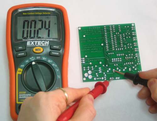
You might be asking, "What is continuity?" But don't worry, it's quite simple! Continuity means, are two things electrically connected. So if two electronic parts are connected with a wire, they are continuous. If they are connected with cotton string, they are not: while they are connected, the cotton string is not conductive.
You can always use a resistance-tester (ohmmeter) to figure out if something is connected because the resistance of wires is very small, less than 100 ohms, usually. However, continuity testers usually have a piezo buzzer which beeps. This makes them very useful when you want to poke at a circuit and need to focus on where the probes are instead of staring at the meter display.
For some basic circuits you can just look to see where the wires go to determine continuity but it's always wise to use a multimeter. Sometimes wires break or you're tired and can't easily follow all the PCB traces. I use continuity check all the time!
Continuity is one of the most important tests. Here are some things it is good for
You can only test continuity when the device you're testing is not powered. Continuity works by poking a little voltage into the circuit and seeing how much current flows, its perfectly safe for your device but if its powered there is already voltage in the circuit, and you will get incorrect readings
Always test to make sure your meter is working before starting the test by brushing the two tips together, and verifying you hear the beep. Maybe the battery is low or its not in the right mode.
Continuity is non-directional, you can switch probes and it will be the same.
If you are testing two points in a circuit and there is a (big) capacitor between those points you may hear a quick beep and then quiet. That's because the voltage the meter is applying to the circuit is charging up the capacitor and during that time the meter 'thinks' its continuous (essentially)
Small resistors (under 100 ohms or so) and also all inductors will seem like short circuits to a multimeter because they are very much like wires.
Likewise, continuity doesn't mean "short" it just means very very low resistance. For example, if you have a circuit that draws an Amp from a 5V supply, it will appear to be a 5Ω resistor. If you measure that with your meter it will think its a short circuit, but really its just a high-drain circuit.
First step is to get your multimeter into the correct mode. Look for the icon that looks sort of like a 'sound wave'
Here are three examples. Note that sometimes the mode is "dual" (or possibly more) usage,
![]()
![]()
![]()
Turn the multimeter knob so that it points to this symbol
For a majority of multimeters, you're ready to go, just touch the tips of the probes together so that they make a beeping sound!
Here's a video demonstration
If you can't view embedded videos, click here to download an mp4
Here are some examples covering a couple of different multimeters
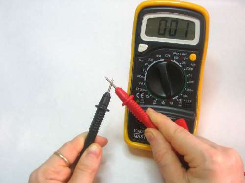
This meter is very simple. When the probes are not touching, the display shows "1"
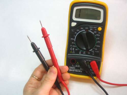
When you touch the tips together, the display changes to a three digit mode (it's displaying resistance, which we will cover later) It also emits a beep
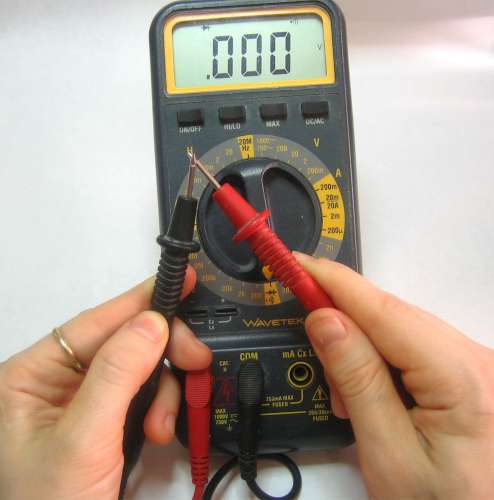
This meter is dual-mode but still very easy to use. Turn the dial to the symbol. When the probes are not touching the display shows "OL" which stands for Open Loop. (Open loop is another way of saying there is no continuity)
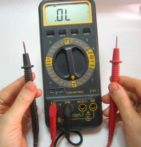
When you touch the probes, the soundwave icon shows up in the display (upper right) and it also shows a number. The number is not the resistance, actually...its the voltage (look for the V in the right hand side for Volts). This is because this mode is also a Diode Test (which will be discussed later)
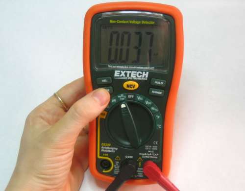
This meter is triple-mode and requires an extra step to get to the continuity function. Click on the image to get a closer view of the triple-mode. After you dial to this mode you must press the Mode button, the wave icon will then appear in the display.
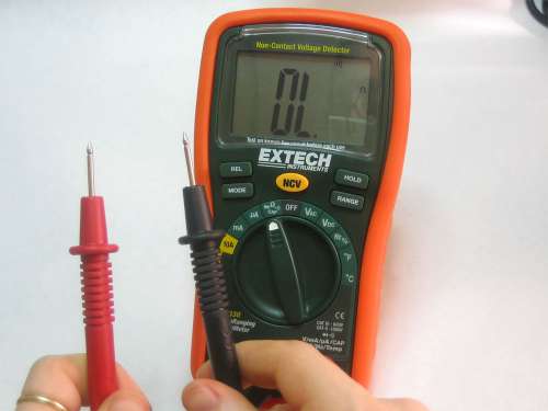
You can see the wave icon in the top right as expected. This meter also displays OL (I've noticed that nicer meters do this)
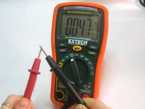
Unlike the other meter, this one displays Ohms (see the symbol on the right of the display). The resistance is low (4.7Ohms) but not 0 (the ideal value) because the probes and wires act as resistors. Usually with these sorts of meters they will beep whenever resistance is under 100 ohms or so.
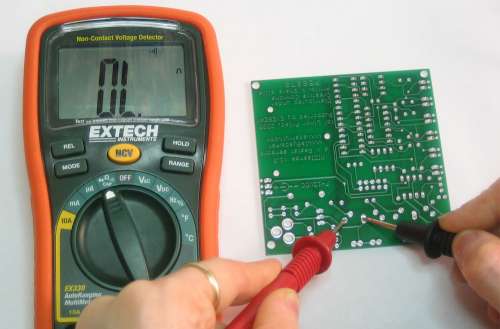
The second test shows that these two points are connected

Clamp meters allow for measurement of current, without needing to disconnect the wires where the measurement occurs. By simply clamping the wire, you can get the measurement, and not cut the circuit. When using a multitester or a digital multimeter, the circuit has to be cut. In contrast, using a clamp meter, current can be measured by clamping a live wire over its sheath. In addition to its simple operation, it allows safe measurement of a higher current.
Clamp meters feature low internal resistance and have both a positive and negative lead. High current flow can indicate a short circuit, a defective component, or an unintentional ground. Low current flow can indicate high resistance, or poor current flow within the circuit. Both types of clamp meters (digital and analog) are designed to measure levels of direct current (DC) and alternating current (AC). Most products have built in sensors. Some clamp meters can test diodes or transistors while others can monitor thermocouples or resistance temperature detector (RTD) values. Some may adjust sampling rates automatically, display status information as a bar graph, and measure decibel (dB) readings. Our specialty clamp meters provide special measurement types and optional features. Some can test diodes or transistors. Others can monitor thermocouples or resistance temperature detector (RTD) values. Programmable clamp meters provide internal data storage and will allow you to establish activation triggers. Clamp meters are extremely useful and allow for many types of safe electrical testing.
Please visit Fluke Website for your information.